Do you have a question about the Associated Electrics XP3G and is the answer not in the manual?
Details on advanced data modes, frequency hopping, security binding, and failsafe features.
Improved data format for faster, reliable transmission with reduced power consumption.
Advanced frequency-hopping for increased safety and interference-free communication.
Ensures transmitter and receiver bind only to each other, preventing interference.
System returns channels to pre-programmed positions upon signal loss.
Lists advanced 2.4GHz technology, trim adjustments, servo reversing, and dual-rate.
Highlights the receiver's compact size and compatibility with specific transmitters.
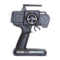
Diagram showing the transmitter's antenna location and function.
Diagram showing the transmitter's battery level indicator LEDs.
Diagram illustrating the throttle ATV control for servo travel.
Diagram showing the servo reversing switches for direction control.
Diagram of the steering trim knob for neutral position adjustment.
Diagram of the throttle trim knob for neutral position adjustment.
Diagram showing the steering D/R control for travel adjustment.
Diagram showing the AUX button and external charging jack.
Diagram of the binding switch used for pairing.
Diagram showing the main steering wheel control.
Diagram illustrating the transmitter's power switch.
Diagram of the throttle trigger for movement control.
Diagram showing the battery cover for access.
Three LEDs indicate battery voltage. Red flashing means recharge/replace.
Allows independent adjustment of maximum throttle servo travel in each direction.
Reverses servo rotation direction. Switches are recessed to prevent accidental movement.
Allows small adjustments to steering for straight running in neutral.
Allows small adjustments to throttle neutral position.
Adjusts the amount of steering servo travel, +/-.
Provides an extra function for additional controls (XP3G only).
Used when charging NiMH rechargeable batteries.
Binding button on the transmitter for binding process.
Controls the vehicle's steering.
Slide to turn the transmitter ON or OFF.
Pull or push to control vehicle movement forward or backward.
Slide to remove the cover to remove or install batteries.
Instructions for replacing or installing AA batteries in the transmitter.
Procedure for inserting batteries into the receiver battery holder.
Diagram showing receiver, servos, ESC, and battery pack connections.
Diagram showing receiver, servos, and battery holder connections.
Important notes on handling the antenna wire to maintain radio range.
Step-by-step guide to manually bind the transmitter and receiver.
Explanation of LED signals during and after the binding process.
Procedure to customize steering and throttle positions for signal loss.
Method to verify the failsafe settings are working correctly.
Guidance on setting throttle and steering F/S for different car types.
Procedure for powering on the transmitter and receiver for failsafe setup.
Pressing and holding the receiver binding button for failsafe.
Adjusting throttle and steering to the desired failsafe positions.
Releasing the button and observing LED changes for confirmation.
How to reverse individual servo output direction using switches.
Adjusting steering neutral position and confirming servo travel.
Adjusting throttle neutral position and overall servo travel.
Independent adjustment of throttle and brake servo travel.
Adjusting the amount of steering servo travel for different driving styles.
Details on limits for Class B digital devices and preventing harmful interference.
Assures continued compliance; modifications void authority. Subject to two conditions.
Complies with RF exposure limits; requires minimum 20cm separation from body.
Precautions against rain, lightning, alcohol, and extreme temperatures.
Ensure sufficient battery power and remove batteries for long-term storage.
Product designation, type, manufacturer name, and address.
List of standards applied for R&TTE Directive compliance evaluation.
Details on who is responsible for the declaration and contact information.
Information on product quality, testing, and where to find product details.
Details on the one-year warranty, coverage, and exclusions.
Instructions on how to pack and return items for warranty service.
Troubleshooting steps for 'No Power' problem in radio or receiver.
Solutions for vehicle not responding due to radio or receiver issues.
Troubleshooting steps for reduced radio range and antenna problems.
Solutions for servo not responding, including wiring and connections.
| Brand | Associated Electrics |
|---|---|
| Model | XP3G |
| Category | Remote Control |
| Language | English |