CAUTION: NEVER CHARGE A BATTERY AT VOLTAGE RATES ABOVE THAT OF THE BATTERY.
3. The battery will show little or no amperage at the start of the charging process. This will continue until the sulfation begins to
break down.
CAUTION: AS THE SULFATION BREAKS DOWN, THE AMPERAGE MAY RAPIDLY RISE. CONSTANT
ATTENTION MUST BE OBSERVED TO PREVENT SERIOUS OVERHEATING OF THE
BATTERY.
4. Lower the charge rate to the lowest rate for the voltage of battery being charged.
5. Charge the battery at this low rate until the electrolyte reaches the fully charged state as described in the tables in your
instruction manual. This may take as long as two or three days.
NOTE: SOME BATTERIES MAY BE SO BADLY SULFATED THEY CAN NOT BE RESTORED TO A NORMAL OPERATING
CONDITION, REGARDLESS OF THE RATE OF CHARGE OR THE LENGTH OF TIME THE CHARGE IS APPLIED. IF THE
BATTERY CANNOT BE RESTORED TO A FULLY CHARGED CONDITION BY A SLOW CHARGING, IT SHOULD BE
REPLACED.
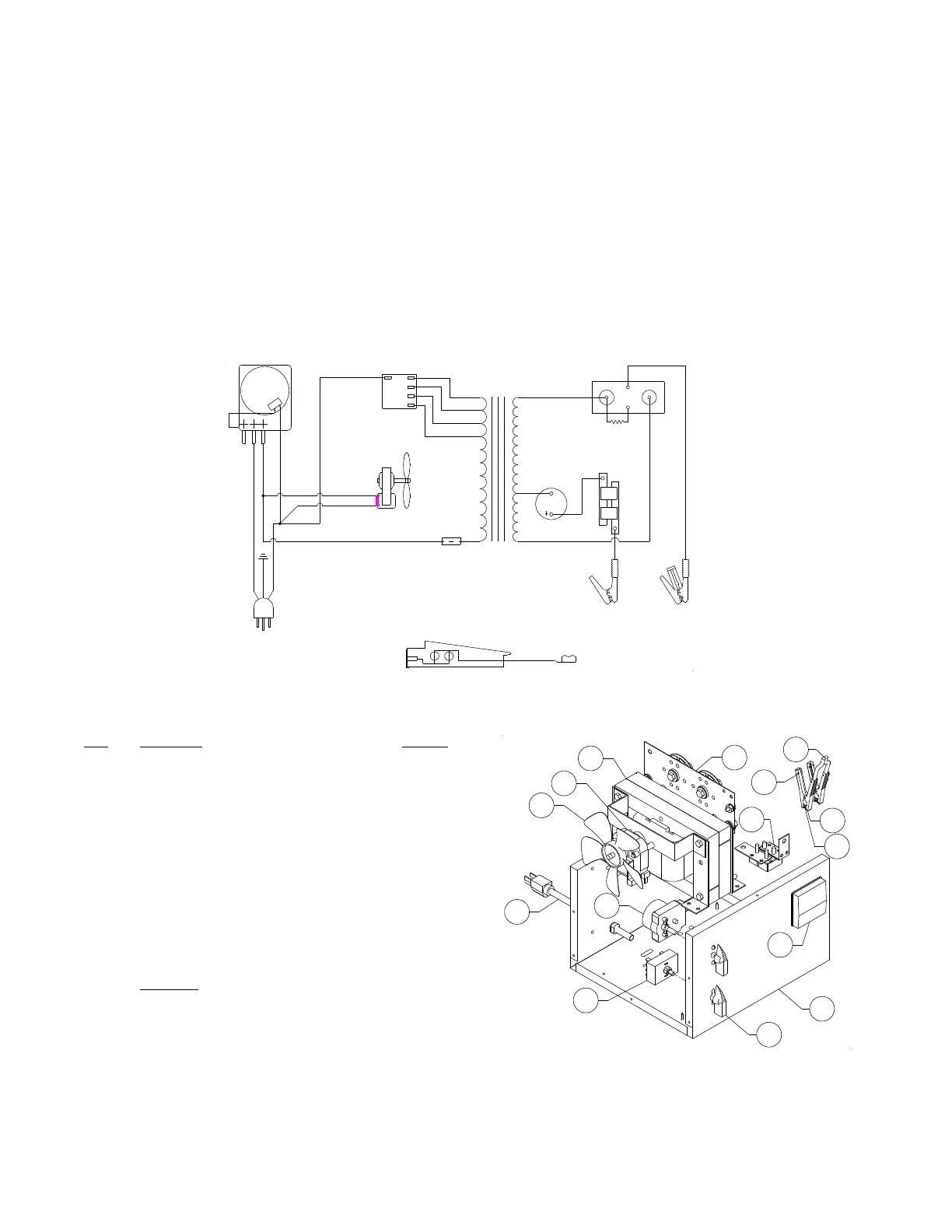
WIRING DIAGRAM
MODEL 6010B PARTS LIST
Item Description Part No.
1 Transformer ......................................................... 611386
2 Rectifier ............................................................... 610364
3 Fan Blade ............................................................ 610189
4 Fan Motor ............................................................ 610190
5 Timer ................................................................... 611245
6 Switch w/knob (1) ................................................ 611187
7 Amps Charge Meter ............................................ 605204
8 AC Cord .............................................................. 611248
9 DC Cable set ....................................................... 611134
10 DC Circuit Breaker (1) ......................................... 610069
11 Front/Base/Back Panel ....................................... 611387
12 Stop/Go Lite ........................................................ 604579
13 Clamps (1 pair, includes jaws) ................................ 6202
14 Jaw Kit (repairs 1 clamp) ..................................... 610970
15 Knob (1) .............................................................. 603147
Not shown
Top Panel ............................................................ 611025
Side Panel (2) ..................................................... 610071
Handle ................................................................. 610057
MAINTENANCE INSTRUCTIONS
Worn clamps and jaws should be replaced. Worn parts can lead to poor connections and present a safety hazard. See parts list for part
number of jaw and clamp kits. Any Maintenance or repair of this unit that involves disassembly of the cabinet should be done only by a
qualified serviceman. Incorrect reassembly may result in a risk of electric shock when the unit is subsequently used.