IB-2003 Series 40 Transfl ite-Stationary Conveyor
61
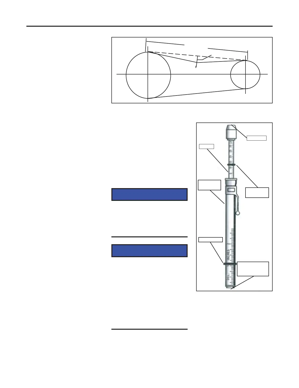
Appendix C: Belt Tension Instructions
Belt Tension Gauge
Instructions
Use the following procedure to
measure v-belt tension.
1. Lockout/tagout all power.
2. Measure the belt span
length of the drive (see
drawing).
3. Set the large O-ring on the
body of the tension gauge
at the dimension equal to
1/64” for every inch of span
length.
For example:
32” belt span
1/64 x 32 = 1/2”
4. Set the O-ring on the
plunger at zero (0) against
the body of the tension
gauge.
5. Press the v-belt tension
gauge perpendicular to the
belt at the midpoint of the
belt span.
Defl ect the belt until the
bottom of the large O-ring
is even with the top of the
next belt, or the bottom of
a straight edge laid across
the top of the other belt(s)
on the drive. Release
pressure and read pounds
of force used at O-ring on
plunger.
Belt Span
Force
Defl ection
6. Compare the force
required in step 5 with the
ranges in the table on page
C-3.
Tighten or loosen belts as
needed to bring them
within the recommended
ranges.
NOTICE
The proper tension for v-belt
drive is the lowest tension at
which the belts will not slip
under peak load conditions.
NOTICE
For new belts, tighten to the
initial installation defl ection
force shown in the table
below. Check tension
frequently during the fi rst
24 hours of operation.
Subsequent retensioning
should fall between the
minimum and maximum
forces shown in the table.
Single Barrel V-belt Tensiometer
Measuring Belt Span and Defl ection Force
Place this end at
the midpoint of
belt span.
Small O-ring
(set at zero)
Hold here
Plunger
Tension
gauge body
Large O-ring
 Loading...