This document serves as the user's manual for the Aston® Overhead Two Post Lift, model AL-100RH. This electro-hydraulic lift is designed for safely raising automotive vehicles and has a rated capacity of 10,000 lbs. (4.5T). The manual provides essential information for installation, operation, and maintenance to ensure safe and proper use of the equipment.
Function Description
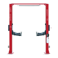
The Aston® AL-100RH is an electro-hydraulic overhead two-post lift intended for lifting automotive vehicles. Its primary function is to elevate vehicles to a comfortable working height for maintenance and repair tasks. The lift operates using an electro-hydraulic system, ensuring smooth and controlled raising and lowering movements. It features an equalizing system with cables to ensure level movement of both carriages, and a collision prevention switch to avoid contact between the vehicle roof and the cross member. Automatic arm restraints lock once the lift is raised, preventing accidental swivel under load. Pipe break valves are integrated into the hydraulic cylinders to prevent sudden lowering in case of a rapid pressure drop, and a pressure relief valve limits the hydraulic working pressure to a maximum of 150 bar. The lift is designed for both approach directions, with a recommendation to use the short support arms for engaging the engine side of the vehicle for a longer service life.
Important Technical Specifications
The AL-100RH model has a capacity of 10,000 lbs. (4.5T).
Key dimensions include:
- Min. Height: 100 mm
- Max. Lifting Height: 1900 mm
- Overall Height: 3600 mm
- Overall Width: 3384 mm
- Width between Columns: 2760 mm
- Short Arm Length: 680 mm ~ 1020 mm
- Long Arm Length: 860 mm ~ 1300 mm
Performance specifications are:
- Lifting Time: Approx. 50 Sec.
- Lowering Time: Approx. 30 Sec.
The lift requires M18 anchoring bolts and a minimum concrete grade of C20/25 (DIN 1045:2001-07). The motor power is 2.2KW, with a rated current of 14.6A and a fuse protection of 16 A time delay. It operates on a 3~400V+N+PE power supply. The sound pressure level is ≤75dB(A). The hydraulic oil recommended is N32 or N46, non-foaming, non-detergent hydraulic fluid (Texaco HD46 or equivalent), and the unit holds twelve quarts of fluid.
Usage Features
The lift is designed for indoor use only, with an operating ambient temperature range of 41-104°F (5-40°C). Operation is restricted to qualified personnel over 18 years of age.
Safety Features:
- Dead Man's Type Control: Requires the operator to hold controls in the engaged position for raising or lowering.
- Equalizing System: Cables ensure level movement of both carriages.
- Collision Prevention Switch: A rope-operated limit switch prevents vehicle roof contact with the cross member.
- Pinch Point Protection: Support arms automatically stop at 120 mm above bottom position during lowering, requiring a separate "Lower to bottom position" button press for full descent, accompanied by an audible signal.
- Automatic Arm Restraint: Arms lock automatically when the lift is raised to prevent swivel under load.
- Pipe Break Valve: Prevents sudden lowering in case of rapid pressure drop.
- Pressure Relief Valve: Limits hydraulic working pressure to 150 bar.
Operational Procedures:
- Before driving a vehicle onto the lift, arms must be positioned to the drive-through position for unobstructed clearance.
- Vehicle positioning requires applying the parking brake and carefully positioning the vehicle midway between adapters.
- The disk adapters must be positioned under the vehicle manufacturer's recommended lift points, ensuring even contact on all four points.
- Arm restraints must be checked for engagement once the disk adapters contact the lift points.
- Vehicle doors must be closed during raising and lowering cycles.
- The lift must be locked by pressing the lowering lever to relieve hydraulic pressure and allow latches to set tightly in a lock position before working under the vehicle.
- To lower the lift, it must first be raised slightly to clear the safety racks, then the safety release handle pulled down, and the lever at the power unit pressed.
Maintenance Features
The manual outlines a comprehensive maintenance schedule to ensure the lift's longevity and safe operation.
Daily Pre-Operation Check (8 Hours):
- Check safety lock audibly and visually.
- Inspect safety latches for free movement and full engagement.
- Check hydraulic connections and hoses for leakage.
- Inspect chain and cable connections for bends, cracks, and looseness.
- Check for frayed cables in both raised and lowered positions.
- Check snap rings at all rollers and sheaves.
- Tighten all bolts, nuts, and screws.
- Check wiring and switches for damage.
- Keep the base plate free of dirt, grease, or corrosive substances.
- Check the floor for stress cracks near anchor bolts.
Weekly Maintenance (40 Hours):
- Check swing arm restraints.
- Torque anchor bolts to 150 ft-lbs for 3/4" anchor bolts (without using an impact wrench).
- Check hydraulic oil level.
- Check and tighten bolts, nuts, and screws.
- Inspect cylinder puller assembly for free movement or excessive wear.
- Inspect cable pulley for free movement and excessive wear.
- Check cylinder mount for looseness and damage.
Yearly Maintenance:
- Lubricate chains.
- Grease rub blocks and column surface contacting rub blocks.
- Change hydraulic fluid. This interval may be shorter in dusty environments.
- Items to be performed by a trained maintenance expert: replace hydraulic hoses, chains, rollers, cables, sheaves, and rebuild/replace air/hydraulic cylinders and pumps/motors as required.
- Check hydraulic and air cylinder rod and rod end (threads) for deformation or damage.
The manual also emphasizes the importance of cleanliness to prevent contamination, which is a frequent cause of hydraulic equipment malfunction.