0000138174 rev.1.1 5
5.2 STATE MACHINE DIAGRAM
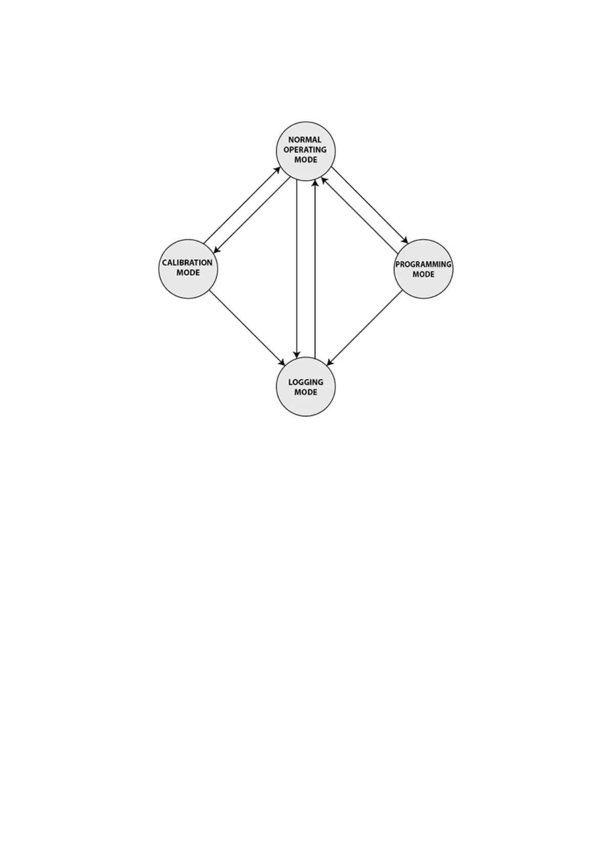
When the pump powers on, it will resume operation in normal operating mode. The current state is shown on the LCD.
The pump has four modes of operation: Normal Operating, Calibration, Programming and Logging. The pump can move
from any one state to another. Image 5 shows this.
Image 5. State Diagram
5.3 CONFIGURING THE PUMP
5.3.1 ADDRESS
The address of the pump in the bus is set on the pump (0x00 only read in holding register).
The factory default is 0x01. However if more than one pump wants to be implemented both ID_Address values must not
match. This situation can be avoided by changing from device.
5.3.2 COMMUNICATIONS SETUP
It's possible enabling or disabling the communication, change the watchdog configuration, watchdog time, address, parity
and baudrate.
5.4 WATCHDOG TIME OUT
The watchdog is a timer implemented in the pump to check if the communications in the bus is still alive. When the pump
loses communication for a time greater than the watchdog_time, the pump perform the action selected in: wdg config.,
wdg alarm, hardware reset, com. reset and stop dosage.