1-281-28
1-281-28
1-28
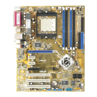
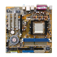
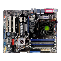
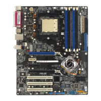
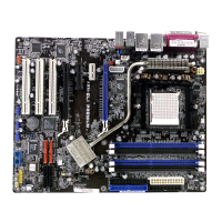
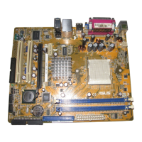
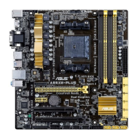
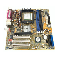
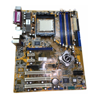
Chapter 1: Product introductionChapter 1: Product introduction
Chapter 1: Product introductionChapter 1: Product introduction
Chapter 1: Product introduction
12.12.
12.12.
12.
Front panel audio connector (10-1 pin FP_AUDIO)Front panel audio connector (10-1 pin FP_AUDIO)
Front panel audio connector (10-1 pin FP_AUDIO)Front panel audio connector (10-1 pin FP_AUDIO)
Front panel audio connector (10-1 pin FP_AUDIO)
This connector is for a chassis-mounted front panel audio I/O module
that supports legacy AC ‘97 audio standard. Connect one end of the
front panel audio I/O module cable to this connector.
11.11.
11.11.
11.
Chassis intrusion connector (4-1 pin CHASSIS)Chassis intrusion connector (4-1 pin CHASSIS)
Chassis intrusion connector (4-1 pin CHASSIS)Chassis intrusion connector (4-1 pin CHASSIS)
Chassis intrusion connector (4-1 pin CHASSIS)
This connector is for a chassis-mounted intrusion detection sensor or
switch. Connect one end of the chassis intrusion sensor or switch
cable to this connector. The chassis intrusion sensor or switch sends a
high-level signal to this connector when a chassis component is
removed or replaced. The signal is then generated as a chassis
intrusion event.
By default, the pins labeled “Chassis Signal” and “Ground” are shorted
with a jumper cap. Remove the jumper caps only when you intend to
use the chassis intrusion detection feature. See related BIOS item in
page 2-42.
A8N5X
A8N5X Chassis intrusion connector
CHASSIS
+5VSB_MB
Chassis Signal
GND
(Default
A8N5X
A8N5X Front panel audio connector
FP_AUDIO
BLINE_OUT_L
MIC2
Line out_R
Line out_L
BLINE_OUT_R
NC
MICPWR+5VA
AGND
 Loading...