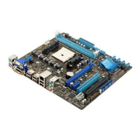
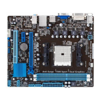
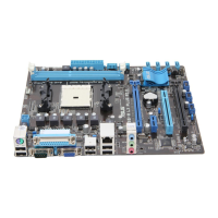
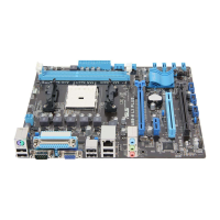
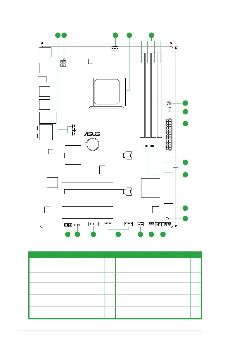
1.5.3 Motherboard layout
1.5.4 Layout contents
Connectors/Jumpers/Slots/LED Page Connectors/Jumpers/Slots/LED Page
1. Power, CPU and chassis fan connectors
(3-pin PWR_FAN, 4-pin CPU_FAN, and 4-pin
CHA_FAN1/2)
1-20 9. Standby power LED (SB_PWR) 1-27
2. ATX power connectors (24-pin EATXPWR,
4-pin ATX12V)
1-21 10. System panel connector (20-8 pin PANEL) 1-23
3. AMD FM1 socket
1-7 11. Clear RTC RAM (3-pin CLRTC) 1-17
4. DDR3 DIMM slots
1-10 12. USB 2.0 onnectors (10-1 pin USB78, USB910) 1-25
5. MemOK! switch
1-26 13. Serial port connector (10-1 pin COM1) 1-22
6. DRAM LED (DRAM_LED)
1-27 14. Digital audio connector (4-1 pin SPDIF_OUT) 1-24
7. SATA 6.0Gb/s connectors (7-pin SATA6G_1~6)
1-22 15. Front panel audio connector (10-1 pin AAFP) 1-24
8. USB 3.0 connector (20-1 pin USB3_34)
1-25
F1A75
PCIEX16_1
PCIEX16_2
PCIEX1_2
PCIEX1_1
PCI1
PCI2
PCI3
USB78 USB910
USB3_34
PANEL
SPDIF_OUT
AAFP
CPU_FAN
CHA_FAN1
PWR_FAN
CHA_FAN2
Lithium Cell
CMOS Power
Super
I/O
AUDIO
ALC
887
EPU
RTL
8111E
ICS483A
COM1
KBMS
32Mb
BIOS
SB_PWR
CLRTC
22.4cm(8.8in)
30.5cm(12.0in)
AMD
®
A75 FCH
DDR3 DIMM_A1 (64bit, 240-pin module)
DDR3 DIMM_A2 (64bit, 240-pin module)
DDR3 DIMM_B1 (64bit, 240-pin module)
DDR3 DIMM_B2 (64bit, 240-pin module)
LAN1_USB12
USB3_12
USB34
USB56
SPDIF_O2
SATA6G_5
SATA6G_6
SATA6G_1
SATA6G_2
MemOK!
DRAM_LED
SOCKET FM1
ATX12V
SATA6G_3
SATA6G_4
EATXPWR
1 2 41 3
8
2
5
5
9
15 14 13 12 111 10
7
7
6
Chapter 1: Product introduction1-6