1-2
Chapter 1: Product introduction
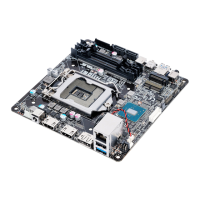
Clear RTC RAM (2-pin CLRTC)
ThisheaderallowsyoutocleartheCMOSRTCRAM
dataofthesystemsetupinformationsuchasdate,time,
andsystempasswords.
To erase the RTC RAM:
1. TurnOFFthecomputerandunplugthepower
cord.
2. Useametalobjectsuchasascrewdrivertoshort
thetwopins.
3. PlugthepowercordandturnONthecomputer.
4. Holddownthe<Del>keyduringthebootprocess
andenterBIOSsetuptore-enterdata.
+3V_BAT
GND
PIN 1
Ifthestepsabovedonothelp,removetheonboardbatteryandshortthetwopinsagain
tocleartheCMOSRTCRAMdata.AfterclearingtheCMOS,reinstallthebattery.
CPU and chassis fan connectors (4-pin CPU_FAN, 4-pin CHA_FAN )
Connectthefancablestothefanconnectorsonthemotherboard,ensuringthatthe
blackwireofeachcablematchesthegroundpinoftheconnector.
Donotforgettoconnectthefancablestothefanconnectors.Insufcientairowinside
thesystemmaydamagethemotherboardcomponents.Thesearenotjumpers!Donot
placejumpercapsonthefanconnectors!TheCPU_FANconnectorsupportsaCPUfan
ofmaximum1A(12W)fanpower.
Intel
®
LGA1151 CPU socket
InstallIntel
®
LGA1151CPUintothissurfacemountLGA1151socket,whichis
designedfor6thGenerationIntel
®
Core™i7/i5/i3,Pentium
®
,andCeleron
®
processors
Formoredetails,refertoCentral Processing Unit (CPU).
DDR4 SO-DIMM slots
Install2GB,4GB,8GB,and16GBnon-ECCun-bufferedDDR4SO-DIMMsinto
theseDIMMsockets.
M.2 SSD connector
ThissocketallowsyoutoinstallanM.2(NGFF)SSDmodule.
ThissocketsupportsMKeyandtype2280storagedevices.
SATA power connector (15-pin SATA_PWRCON)
ThisconnectorisfortheSATApowercable.Thepowercableplugisdesignedto
tthisconnectorinonlyoneorientation.Findtheproperorientationandpushdown
rmlyuntiltheconnectorcompletelyt.ToprovidepowertoyourSATAdevice,
connecttheSATApowercabletothisconnector
 Loading...