1-2
Chapter 1: Product introduction
ATX power connectors (24-pin EATXPWR, 4-pin ATX12V)
CorrectlyorienttheATXpowersupplyplugsintotheseconnectorsandpushdown
rmlyuntiltheconnectorscompletelyt.
•
Forafullyconguredsystem,werecommendthatyouuseapowersupplyunit
(PSU)thatcomplieswithATX12VSpecication2.0(orlaterversion)andprovides
aminimumpowerof300W.
•
Ifyouareuncertainabouttheminimumpowersupplyrequirementforyoursystem,
refertotheRecommendedPowerSupplyWattageCalculatorathttp://support.
asus.com/PowerSupplyCalculator/PSCalculator.aspx?SLanguage=en-usfor
details.
CPU and chassis fan connectors (4-pin CPU_FAN, 4-pin CHA_FAN)
Connectthefancablestothefanconnectorsonthemotherboard,ensuringthatthe
blackwireofeachcablematchesthegroundpinoftheconnector.
Donotforgettoconnectthefancablestothefanconnectors.Insufcientairowinside
thesystemmaydamagethemotherboardcomponents.Thesearenotjumpers!Donot
placejumpercapsonthefanconnectors!TheCPU_FANconnectorsupportsaCPUfan
ofmaximum2A(24W)fanpower.
Onlythe4-pinCPUfansupportstheASUSFanXpertfeature.
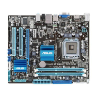
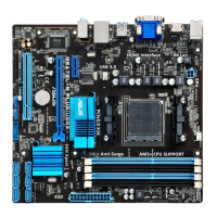
AMD
®
AM3+ CPU socket
InstallAMD
®
CPUintothissurfacemountAM3+socket,whichisdesignedforAMD
®
FX™
Series/Phenom™II/Athlon™II/Sempron™100Series.
Formoredetails,refertoCentral Processing Unit (CPU).
DDR3 DIMM slots
Install1GB,2GB,4GB,and8GB,unbufferedECCandnon-ECCDDR3DIMMs
intotheseDIMMsockets.
Formoredetails,refertoSystem memory.
Clear RTC RAM (2-pin CLRTC)
ThisheaderallowsyoutocleartheCMOSRTCRAMdataofthesystemsetup
informationsuchasdate,time,andsystempasswords.
To erase the RTC RAM:
1. TurnOFFthecomputerandunplugthepowercord.
2. Useametalobjectsuchasascrewdrivertoshortthetwopins.
3. PlugthepowercordandturnONthecomputer.
4. Holddownthe<Del>keyduringthebootprocessandenter
BIOSsetuptore-enterdata.
CLRTC
+3V_BAT
GND
PIN 1
 Loading...