2-26
Chapter 2: Hardware information
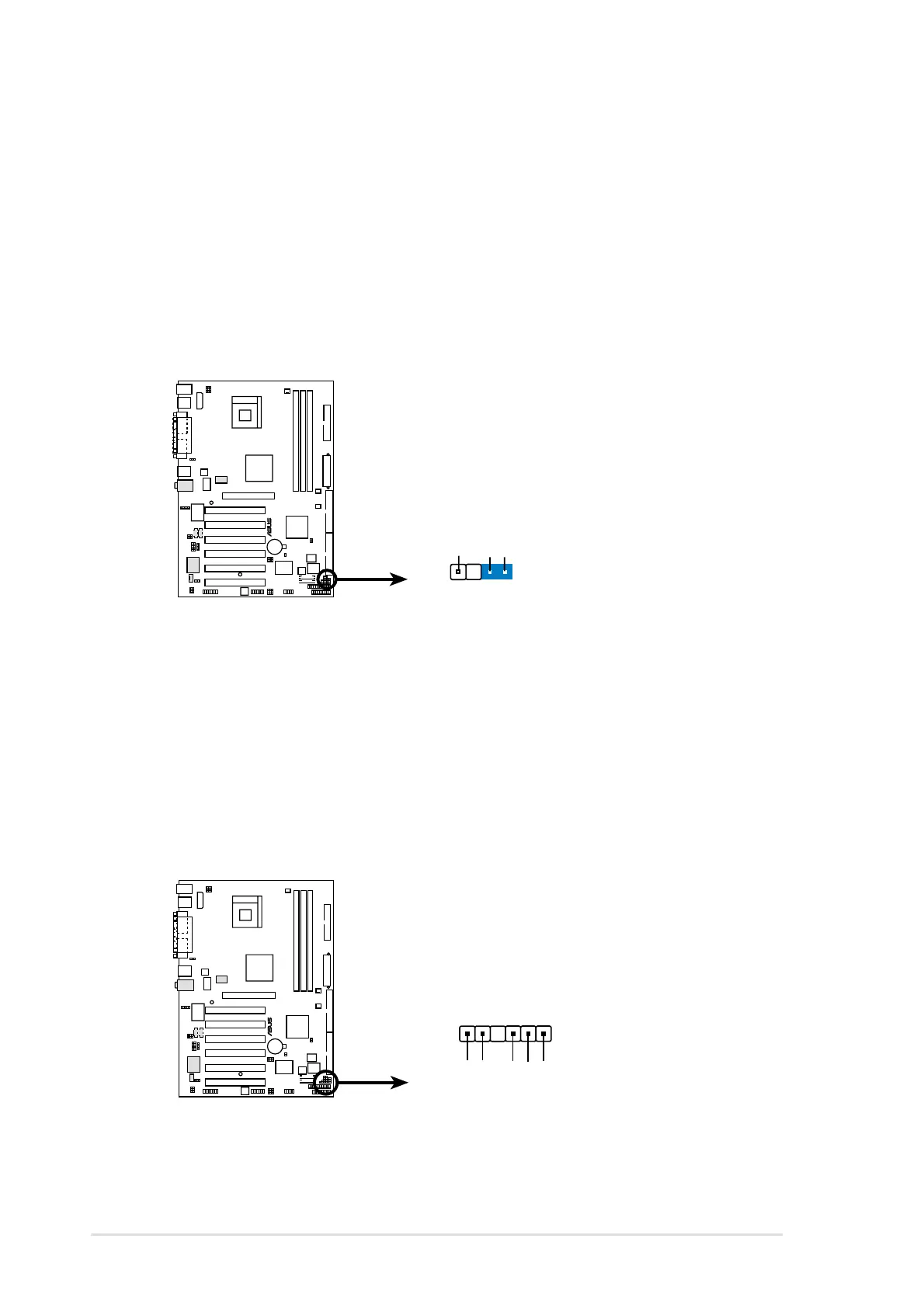
4. Chassis intrusion connector (4-1 pin CHASSIS)
This lead is for a chassis designed with intrusion detection feature.
This requires an external detection mechanism such as a chassis
intrusion sensor or microswitch. When you remove any chassis
component, the sensor triggers and sends a high-level signal to this
lead to record a chassis intrusion event.
By default, the pins labeled “Chassis Signal” and “Ground” are shorted
with a jumper cap. If you wish to use the chassis intrusion detection
feature, remove the jumper cap from the pins.
5. SMBus connector (6-1 pin SMB)
This connector allows you to connect SMBus (System Management
Bus) devices. Devices communicate with an SMBus host and/or other
SMBus devices using the SMBus interface. SMBus is a specific
implementation of an I
2
C bus, a multi-device bus that allows multiple
chips to connect to the same bus and enable each one to act as a
master by initiating data transfer.
P4B533
®
P4B533 SMBus Connector
SMB
1
SMBCLK
Ground
SMBDATA
+3V
FLOATING
P4B533
®
P4B533 Chassis Intrusion Connector
CHASSIS
+5VSB_MB
Chassis Signal
GND
 Loading...