EasyManuals Logo

Asus P5GC-VM User Manual

Asus P5GC-VM
94 pages
To Next Page IconTo Next Page
To Previous Page IconTo Previous Page
Page #41 background imageLoading...
Page #41 background image
ASUS P5GC-VM 1-29
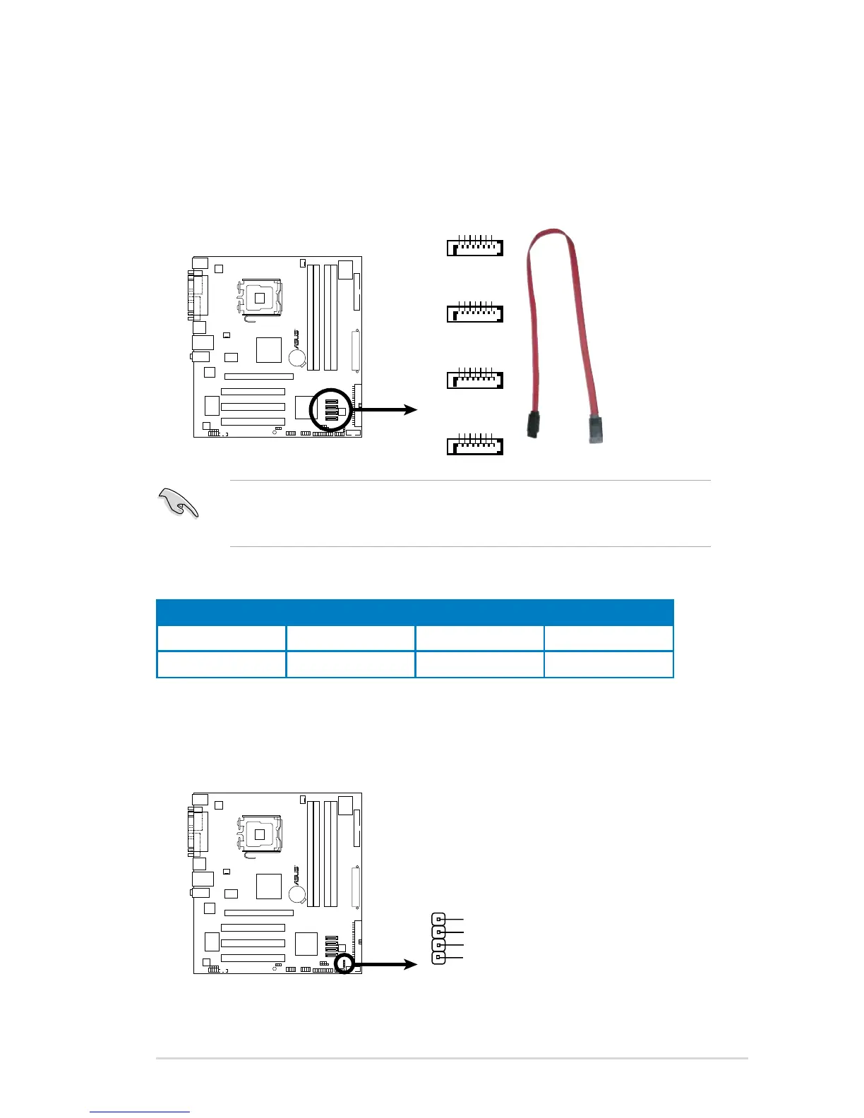
3. Serial ATA connectors (7-pin SATA1 [red], SATA2 [red], SATA3 [black],
SATA4 [black])
These connectors are for the Serial ATA signal cables for Serial ATA hard disk
drives.
When using the connectors in Standard IDE mode, connect the primary (boot)
hard disk drive to the SATA1/2 connector. Refer to the table below for the
recommended SATA hard disk drive connections.
Serial ATA hard disk drive connection
Connector Color Setting Use
SATA1/2 Red Master Boot disk
SATA3/4 Black Slave Data Disk
P5GC-VM
R
P5GC-VM
SATA Connectors
GND
RSATA_TXP1
RSATA_TXN1
GND
RSATA_RXP1
RSATA_RXN1
GND
SATA1
GND
RSATA_TXP2
RSATA_TXN2
GND
RSATA_RXP2
RSATA_RXN2
GND
SATA2
GND
RSATA_TXP3
RSATA_TXN3
GND
RSATA_RXP3
RSATA_RXN3
GND
SATA3
GND
RSATA_TXP4
RSATA_TXN4
GND
RSATA_RXP4
RSATA_RXN4
GND
SATA4
4. Speaker connector (4-pin SPEAKER)
This 4-pin connector is for the chassis-mounted system warning speaker. The
speaker allows you to hear system beeps and warnings.
P5GC-VM
R
P5GC-VM
Speaker Out Connector
SPEAKER
+5V
GND
GND
Speaker Out
1

Table of Contents

Questions and Answers:

Question and Answer IconNeed help?

Do you have a question about the Asus P5GC-VM and is the answer not in the manual?

Asus P5GC-VM Specifications

General IconGeneral
BrandAsus
ModelP5GC-VM
CategoryMotherboard
LanguageEnglish

Related product manuals