2-26 Chapter 2: Hardware information
Connect the right-angle side of SATA
signal cable to SATA device. Or you may
connect the right-angle side of SATA
cable to the onboard SATA port to avoid
mechanical conict with huge graphics
cards.
•
These connectors are set to Standard IDE mode by default. In Standard
IDE mode, you can connect Serial ATA boot/data hard disk drives to these
connectors. If you intend to create a Serial ATA RAID set using these
connectors, set the Congure SATA as item in the BIOS to [RAID]. See
section 3.3.6 Storage Conguration for details.
• Before creating a RAID set, refer to 4.4.3 Intel
®
RAID congurations or
the manual bundled in the motherboard support DVD.
• When using the connectors in Standard IDE mode, connect the primary
(boot) hard disk drive to the SATA1/2 connector. Refer to the table below
for the recommended SATA hard disk drive connections.
right angle side
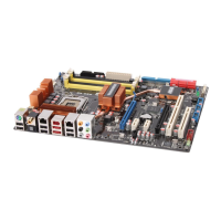
3. ICH10R Serial ATA connectors [red] (7-pin SATA1-6)
These connectors are for the Serial ATA signal cables for Serial ATA hard disk
drives and optical disc drives.
If you installed Serial ATA hard disk drives, you can create a RAID 0, 1, 5,
and 10 conguration with the Intel
®
Matrix Storage Technology through the
onboard Intel
®
ICH10R RAID controller.
Serial ATA hard disk drive connection
Connector Color Setting Use
SATA 1/2 Red Master Boot disk
SATA 3/4 Red Slave Boot/Data disk
SATA 5/6 Red Master Boot disk
 Loading...