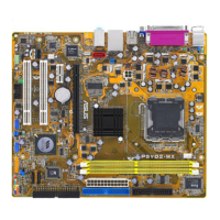
ASUS P5VD2-VM/P5V-VM SE DH 1-35
11. Front panel audio connector (10-1 pin AAFP)
This connector is for a chassis-mounted front panel audio I/O module that
supports either High Denition Audio or legacy AC ‘97 audio standard.
Connect one end of the front panel audio I/O module cable to this connector.
• Use a chassis that provides a high-denition audio front panel audio
I/O to use the high-denition audio features.
• The default setting of this connector is legacy AC’97 audio, if you want to
use the High-Denition (Azalia) audio features, set the Front Panel Support
Type in the BIOS to Azalia.
12. Chassis intrusion connector (4-1 pin CHASSIS)
This connector is for a chassis-mounted intrusion detection sensor or switch.
Connect one end of the chassis intrusion sensor or switch cable to this
connector. The chassis intrusion sensor or switch sends a high-level signal to
this connector when a chassis component is removed or replaced. The signal
is then generated as a chassis intrusion event.
By default, the pins labeled “Chassis Signal” and “Ground” are shorted with
a jumper cap. Remove the jumper caps only when you intend to use the
chassis intrusion detection feature.

 Loading...