2-38 Chapter 2: Hardware information
12. Chassis intrusion connector (4-1 pin CHASSIS)
This connector is for a chassis-mounted intrusion detection sensor or switch.
Connect one end of the chassis intrusion sensor or switch cable to this
connector. The chassis intrusion sensor or switch sends a high-level signal to
this connector when a chassis component is removed or replaced. The signal
is then generated as a chassis intrusion event.
By default, the pins labeled “Chassis Signal” and “Ground” are shorted with
a jumper cap. Remove the jumper caps only when you intend to use the
chassis intrusion detection feature.
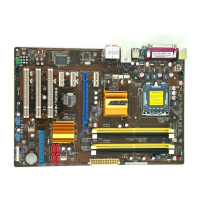
13. CPU, Chassis, and Power Fan connectors (4-pin CPU_FAN, 3-pin
PWR_FAN1, 3-pin PWR_FAN2, 3-pin CHA_FAN1, 3-pin CHA_FAN2)
The fan connectors support cooling fans of 2A (24W max.) at +12V. Connect
the fan cables to the fan connectors on the motherboard, making sure that
the black wire of each cable matches the ground pin of the connector.
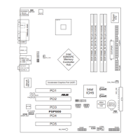
P5W DH DELUXE
®
P5W DH DELUXE Fan connectors
CPU_FAN
CHA_FAN1
PWR_FAN2
GND
Rotation
+12V
CPU_FAN
CHA_FAN2
PWR_FAN2
CHA_FAN1
GND
Rotation
+12V
GND
CPU FAN PWR
CPU FAN IN
CPU FAN PWM
GND
Rotation
+12V
PWR_FAN1
PWR_FAN1
CHA_FAN2
GND
Rotation
+12V
For the rear
chassis
For the side
chassis
For the front
chassis
P5W DH DELUXE
®
P5W DH DELUXE Chassis intrusion connector
CHASSIS
+5VSB_MB
Chassis Signal
GND
(Default)
 Loading...