ix
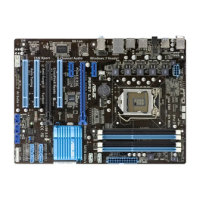
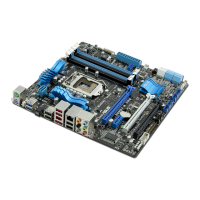
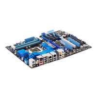
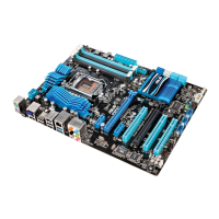
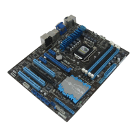
P8P67 LE specications summary
(continued on the next page)
CPU LGA1155 socket for Intel
®
Second Generation Core™ i7 / Core™
i5 / Core™ i3 processors
Supports 32nm CPU
Supports Enhanced Intel
®
SpeedStep Technology (EIST)
Supports Intel
®
Turbo Boost technology 2.0
* The Intel
®
Turbo Boost technology 2.0 support depends on the
CPU types.
** Refer to www.asus.com for Intel
®
CPU support list.
Chipset Intel
®
P67 Express Chipset
Memory 4 x DIMM, max. 32GB, DDR3 2200(O.C.) / 2133(O.C.) /
1866 (O.C.) / 1600 (O.C.) / 1333 / 1066 MHz, non-ECC,
un-buffered memory
Dual-channel memory architecture
Supports Intel
®
Extreme Memory Prole (XMP)
* The maximum 32GB memory capacity can be supported with
8GB or above DIMMs. ASUS will update the memory QVL
once the DIMMs are available in the market.
** Hyper DIMM support is subject to the physical characteristics
of individual CPUs. Some hyper DIMMs only support one
DIMM per channel. Refer to the Memory QVL (Qualied
Vendors List) for details.
*** Due to CPU behavior, DDR3 2200/2000/1800 MHz memory
module will run at DDR3 2133/1866/1600 MHz frequency as
default.
**** Refer to www.asus.com for the latest Memory QVL (Qualied
Vendors List).
***** When you install a total memory of 4GB capacity or more,
Windows
®
32-bit operating system may only recognize less
than 3GB. We recommend a maximum of 3GB system
memory if you are using a Windows
®
32-bit operating
system.
Expansion slots 1 x PCI Express 2.0 x16 slot (blue, single at x16 mode)
1 x PCI Express 2.0 x16 slot (black, at x4 mode, compatible with
PCI Express x1 and x4 devices)
2 x PCI Express 2.0 x1 slots
3 x PCI slots
* Due to the CrossFireX™ limitation, PCIe x16_2 slot must
run at x4 mode to set up a CrossFireX™ conguration. The
default setting is x2 mode. Go to the BIOS setup to change the
settings. See section 2.5.6 Onboard Devices Conguration in
the BIOS for details.
** The PCIe x1 slots share the bandwidth with the PCIe x16_2
slot. Thus, all PCIe x1 slots will be disabled when you install
two CrossFireX™ graphics cards on both the PCIe x16 slots to
set up a CrossFireX™ conguration.
Multi-GPU support Supports ATI
®
Quad-GPU CrossFireX™ technology

 Loading...