Do you have a question about the Asus PRIME Z790-P D4 and is the answer not in the manual?
Precautions before installing motherboard components or changing settings.
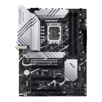
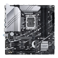
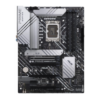
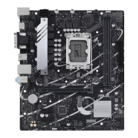
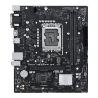
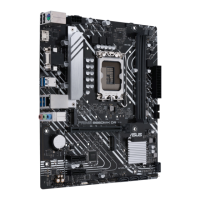
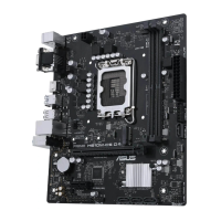
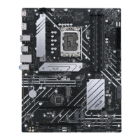
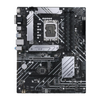
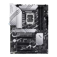
Diagram and labels of the motherboard components and connectors.
Detailed guide on installing the CPU into the LGA1700 socket.
Instructions for installing DDR4 memory modules and recommended configurations.
Information on PCIe slots, their configurations, and VGA setup.
Connectors for CPU/chassis fans and AIO pumps for system cooling.
How to connect the ATX power supply plugs to the motherboard.
Guide to installing M.2 SSD modules and their specifications.
Ports for connecting SATA storage devices like hard drives.
Connecting front panel USB Type-C ports and their data transfer speeds.
Headers for connecting additional USB 3.2 Gen 1 ports.
Headers for connecting additional USB 2.0 ports.
Connectors for addressable RGB WS2812B LED strips.
Header for connecting RGB LED strips for lighting effects.
Procedure to clear the Real Time Clock (RTC) RAM in CMOS.
Header for connecting a COM port module to the motherboard.
Connecting the front panel HD audio module.
Header for connecting the S/PDIF Out module.
Header for Trusted Platform Module (TPM) system for security.
Connects chassis functions like power/reset buttons and LEDs.
Header for connecting an add-on Thunderbolt™ I/O card.
General steps and diagrams for assembling PC components.
Instructions and precautions for installing the CPU into the LGA1700 socket.
Steps for installing CPU heatsink and fan assembly or AIO cooler.
Instructions for installing and removing DDR4 memory modules into DIMM slots.
Steps for installing M.2 SSD cards, including rubber pad usage.
Steps for installing the motherboard into the PC chassis.
How to connect the ATX power supply plugs to the motherboard.
Steps for connecting SATA devices like hard drives.
Connecting front panel connectors for USB, audio, and power/reset buttons.
Instructions for installing PCIe x16 and PCIe x1 expansion cards.
Steps for installing an add-on Thunderbolt™ series card.
Diagrams and descriptions of rear panel I/O and audio connections.
Diagram and list of connectors on the motherboard's rear panel.
How to connect audio devices for various channel configurations.
Information on the vertical M.2 slot for M.2 Wi-Fi modules.
Steps for initial system power-on, POST, and troubleshooting.
Methods to turn off or put the system into sleep mode.
Overview of ASUS UEFI BIOS features and its importance for system settings.
How to enter and navigate the BIOS setup program.
Utility for updating the BIOS using a USB flash drive.
Tool to restore corrupted BIOS files using a USB flash drive.
Explanation of RAID configurations supported by Intel Rapid Storage Technology.
Includes FCC Compliance and HDMI Trademark notices.
Details on ASUS voluntary commercial and statutory legal guarantees.
Contact addresses for ASUS support centers globally.
Information on accessing the ASUS multi-language support website.
| Chipset | Intel Z790 |
|---|---|
| CPU Socket | LGA 1700 |
| Memory Type | DDR4 |
| Maximum Memory | 128GB |
| Memory Slots | 4 x DIMM |
| Form Factor | ATX |
| Wireless | No |
| RAID Support | RAID 0, 1, 5, 10 |
| BIOS | 256 Mb Flash ROM, UEFI AMI BIOS |
| PCIe Slots | 1 x PCIe 5.0 x16, 1 x PCIe 4.0 x16 (x4 mode), 2 x PCIe 3.0 x1 |
| Storage Interface | 4 x SATA 6Gb/s, 3 x M.2 |
| USB Ports | 1 x USB 3.2 Gen 2x2 Type-C, 4 x USB 3.2 Gen 1, 2 x USB 2.0 |
| Network | 2.5Gb Ethernet |
| Audio | Realtek ALC897 |