1-1
1
Product Introduction
1.1 Before you proceed
Take note of the following precautions before you install motherboard components or change
any motherboard settings.
• Unplug the power cord from the wall socket before touching any component.
• Before handling components, use a grounded wrist strap or touch a safely grounded
object or a metal object, such as the power supply case, to avoid damaging them due
to static electricity.
• Hold components by the edges to avoid touching the ICs on them.
• Whenever you uninstall any component, place it on a grounded antistatic pad or in the
bag that came with the component.
• Before you install or remove any component, ensure that the ATX power supply is
switched off or the power cord is detached from the power supply. Failure to do so
may cause severe damage to the motherboard, peripherals, or components.
Unplug the power cord before installing or removing the motherboard. Failure to do so can
cause you physical injury and damage motherboard components.
The pin denitions in this chapter are for reference only. The pin names depend on the
location of the header/jumper/connector.
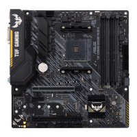
1.2 Motherboard overview
7
DDR5 DIMM_A1 (64bit, 288-pin module)
DDR5 DIMM_A2 (64bit, 288-pin module)
DDR5 DIMM_B1 (64bit, 288-pin module)
DDR5 DIMM_B2 (64bit, 288-pin module)
CPU
DRAM
VGA
BOOT
CPU_OPT
AIO_PUMP
CPU_FAN
CHA_FAN2
CHA_FAN3
CHA_FAN1
COM
PANEL
AAFP
SATA6G_1SATA6G_2SATA6G_3
ATX_PWR
U32G1_89
Super
I/O
2280 2260 2242
2280 2260 2242
PCIEX16_1
PCIEX16_2
PCIEX1
USB_1415 USB_1617
RGB_HEADER
ADD_GEN 2_3
CLRTC
U32G1_2
LAN_USB_11_13
USB_1_5
U32G2_34
U32G2X2_C6
HDMI_DP
DIGI
+VRM
24.4cm(9.6in)
24.4cm(9.6in)
BATTERY
U32_C10
COM_DEBUG
SOCKET AM5
ATX_12V_2 ATX_12V_1
TB_HEADER
AMD
B650
X
PCIE
SATA
4.0 X4
PCIE SATA
5.0 X4 X
M.2_1(SOCKET3)
Audio
Codec
Ethernet
256Mb
BIOS
ADD_GEN 2_1
ADD_GEN 2_2
1
st
AUDIO
BIOS_FLBK
FLBK_LED
SATA6G_4
M.2_2(SOCKET3)
M.2_1(SOCKET3)
M.2_2(SOCKET3)
5
19
8
6
9
1415
18
3
4
2
4 1115
161110 1274
7
13
17
Place this
side towards
the rear of the
chassis
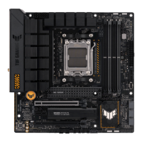
ASUS TUF GAMING B650M-PLUS

 Loading...