ASUS Xeon Installation
Guide 3
Installation Guide
Xeon Processor
R
Xeon Installation Procedure
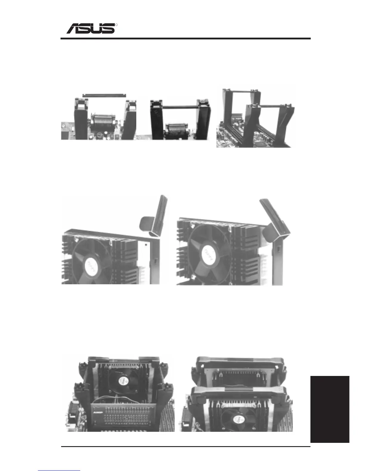
Step 3: Install the Retention Mechanism Brace Bars
Place the retention mechanism brace bar into the groove on the top of the retention
mechanism as shown in the picture below. These pictures are views of the mother-
board and retention mechanism with the ATX connectors away from yourself.
Step 4: Install Cartridge Lifters
Each Xeon processor requires two lifters in order to allow safe removal of the pro-
cessor. The lifters clamps the cartridge on the two holes at each top corner.
(Item 6) Retention Mechanism Brace Bar
Retention mechanism with
brace bar on top
One retention mechanism
with brace bar installed
Both retention mechanisms
with both brace bars installed
One lifter being inserted over the
cartridge from a vertical position
(Item 5) CPU Lifter
Half-colapsed lifter after installation. The
lifter should freely rise and lower.
Step 5: Install a 2nd Processor or Termination Module
The motherboard supports a single or dual processor configuration. When a single
processor configuration is desired, a front side bus termination module is required
on the free slot 2 connector.
Dual processor configuration.
(Item 7) Front Side Bus Termination Module
Single processor configuration with terminator.