Installation & Servicing instructions ATAG A-Series
19
We suggest you design a simple ue gas system and air supply system using table 6.
For further information about the available components of the ue gas and air supply
system we recommend you consult the Duopass Flue system literature.
The ATAG ue gas system is meant, and designed, solely for the use on ATAG central
heating boilers adjusted to Nat gas or LPG. The maximum ue gas temperatures are
below 70°C (full load 80/60°C)
The proper operation may be adversely inuenced by changes of or adjustments to the
correct set up.
Possible warranty claims will not be honoured if incorrect changes result in non compliance
with the installation manual or local rules and regulations.
The ue gas systems described in this document are solely suited for ATAG central
heating boilers of the ATAG boiler range. For this purpose the CE Certicate has been
supplemented under the Gastec nr: 0063BR3405, 0063BQ3021, 0063AS3538 and
0063AU3110. 0063BQ3021, 0063BT3195 en 0063CM3648
The ue gas system should be built up using only ATAG program products. Combinations
with other brands or systems are, without written permission from ATAG Heating, not
permitted.
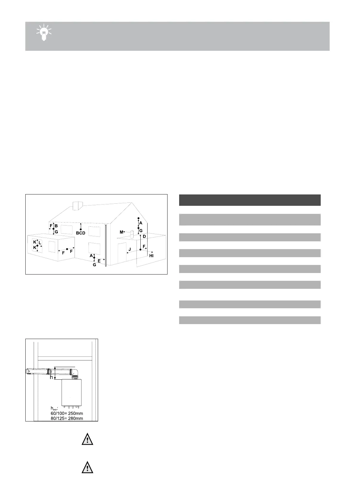
The terminal should be located where dispersal of combustion products is not unimpeded
and with due regard for the damage or discolouration that might occur to parts of the
building in the vicinity (see g 6.8.c).
terminal position for fan assisted boiler
minimum
distance
A
directly below an open window or other opening
(e.g. air brick)
mm 300
B below gutters, soil pipes or drain pipes
mm 75
C
below eaves
mm 200
D below balconies or car port roof
mm 200
E from vertical drain pipes and soil pipes
mm 75
F from internal or external corners
mm 300
G above ground or below balcony level
mm 300
H from a surface facing a terminal
mm 600
I
from a terminal facing a terminal
mm 1200
J
from an opening in the car port (e.g. door
window) into dwelling
mm 1200
K
vertically from a terminal on the same wall
mm 1500
L horizontally from a terminal on the same wall
mm 300
M horizontally from a vertical terminal to a wall
mm 300
Dimensions table 6.8.a
Figure 6.8.c
In certain weather conditions condensation may also accumulate on the outside of the
air inlet pipe. Such conditions must be considered and where necessary insulation of
the inlet pipe may be required.
In cold and/or humid weather water vapour may condense on leaving the ue terminal.
The effect of such ‘plumeing’ must be considered.
The terminal must not be located in a place where it is likely to cause a nuisance.
For protection of combustibles, refer to IS 813 section 9.10.1. where the terminal is less
than 2m (6.6ft) above a pavement or platform to which people have access (including)
any balcony or at roof. The terminal must be protected by a guard of durable material.
A suitable guard is available from the country distributor.
Where a terminal is tted below a window which is hinged at the top, and where
the hinge axis is horizontal, and the window opens outwards, the terminal shall
be 1m below the bottom of the window opening.
If the boiler is to be located under stairs, a smoke alarm meeting the
requirements of I.S. 409 or equivalent must be tted.
Installation height Figure 6.8.d
 Loading...