DIAGRAM 13
A single subwoofer is driven from the 0.1/LFE channel Output of a multichannel processor/monitor controller. For increased dynamic range and
headroom, multiple subwoofers can be connected in series as described in Section
5.5 and 5.6. All panel settings must be set independently for
each subwoofer.
The choice of loudspeaker model and the number of subwoofers required in any system is dependent on room size, mix format and target
calibration level at the listening position. Diagram 11 can be used as a guide to determine suitable partnering system elements from the ATC HiFi
product range.
•
= Recommended. O = Acceptable. For detailed recommendations, please contact your dealer/distributor or ATC.
Surround
loudspeakers/subs
SCM20SL
• •
O
SCM50SL
• •
O
SCM40
O
•
O
SCM100SL
• •
SCM150SL
•
C4 SUB Mk2 1 1-2 2 2-4 4
SCM20SL SCM40 SCM50SL SCM100SL SCM150SL
SECTION SIX
Left/centre/right loudspeakers
80Hz -6dB 0dB 0° +
FREQUENCY
LEVEL
ADJUST FOR BEST
BALANCE
GAIN
PHASE
ADJUST TO FINE
TUNE INTEGRATION
POLARITY
C4 Sub Mk2 – recommended initial settings
when used in a multichannel system
Multichannel Surround/Immersive Audio
6.3
DIAGRAM 11
DIAGRAM 12
Recommended initial settings for the C4 Sub Mk2 when used in a multichannel system are shown in Diagram 12.
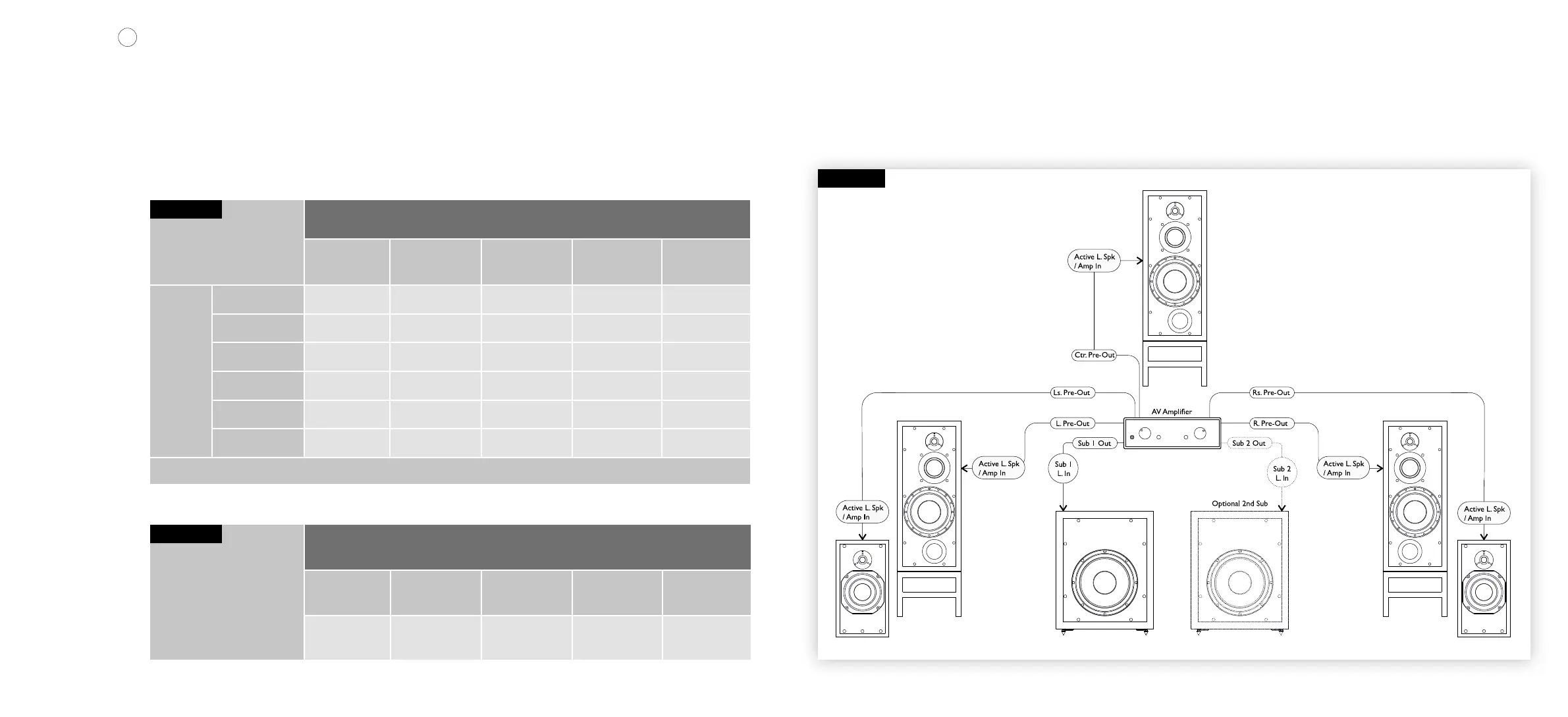
Diagram 13 – Typical Multichannel System wiring. Depending on the AV receiver Output level and number of subwoofers, the Gain switches may
need to be set to 6dB. Further subwoofers can be added to the system by connecting them in a daisy chain using the subwoofer Output sockets.
The system shown is an example and other congurations are available.
 Loading...