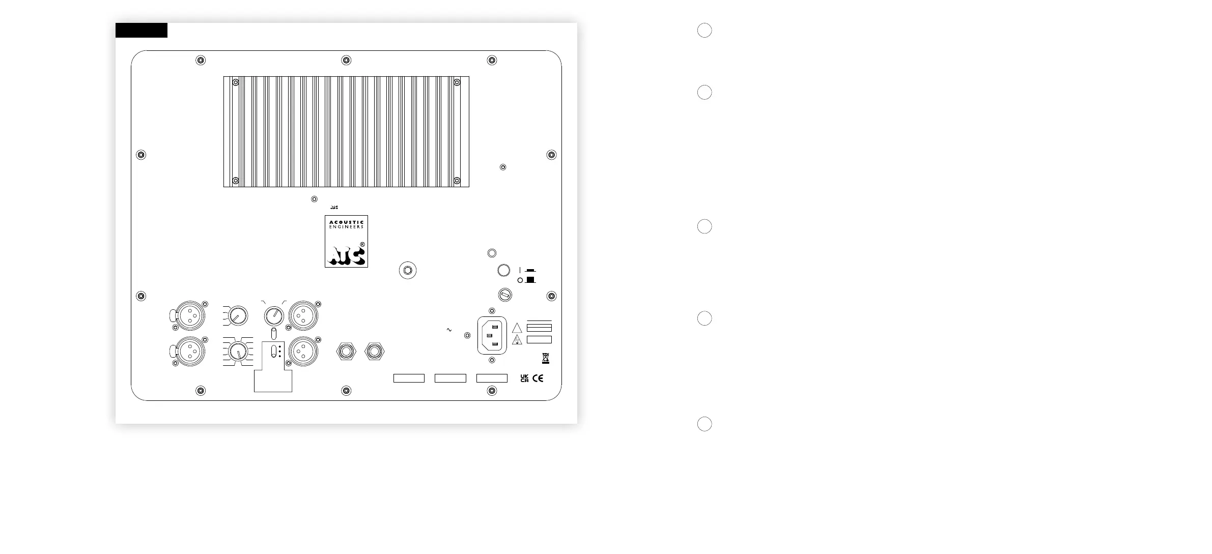
The subwoofer amplier control and connection panel, shown in Diagram 4, provides a range of functions to assist with system integration.
These are explained opposite.
Powers the subwoofer on or o. When the button is in the inward position, the loudspeaker is powered on. When the button is in the outward
position, the subwoofer is powered o.
Sets the overall sensitivity of the subwoofer. Initially, the Level control should be set towards the centre of its range and only adjusted once the
Frequency has been set. If one Input is connected, start with the Gain switch set at +
6dB. If both Inputs are connected, start with the Gain switch
set at 0dB.
An additional +10dB gain setting is included for situations where the preceding equipment can only deliver a low output level. Please note that
increasing the gain does not increase the maximum acoustic output capability of the system.
Please refer to Section 9 – Product Specications for information on system sensitivity.
Sets the overall polarity of the subwoofer and oers an adjustment of the input/output phase. When set to + and 0° the subwoofer will radiate a
positive acoustic pressure for a positive electrical signal at the Input. When set to – and 0° the subwoofer will radiate in the opposite polarity to
the Input. The Phase control allows for ne adjustment of the phase relationship between subwoofer and satellite speakers. This can be thought of
as a delay, allowing for time alignment with other system elements and is useful when physical adjustment of loudspeaker/sub position is limited.
Varies the low pass crossover Frequency as indicated on the control panel. This is the fundamental parameter that denes the integration of the
subwoofer with the satellites. The Frequency control should be set at, or slightly above the specied low frequency cut-o of the satellite speakers.
The “open” setting applies a low pass lter at 320Hz. Select this setting if you will apply the sub low pass crossover lter via an external processor.
All lters are of the type 4th order Linkwitz Riley.
Provides separately buered and fully balanced Outputs with a signal identical to that at the corresponding Input terminals. The Output is unltered
and unaltered in any way, and therefore it is possible to drive a stereo amplier or pair of active loudspeakers from these terminals. Likewise, it is
also possible to drive a second C4 Sub Mk2 from these Outputs. This function allows for an unlimited number of C4 Sub Mk2s to be daisy chained
together, one driving the next.
SECTION FIVE
Power on/off
5.1
Level and Gain
Polarity and Phase
Frequency
Outputs
5.2
5.3
5.4
5.5
WARNING
!
Acoustic Transducer Co. Is a trading name and
Is the registered Trade Mark of Loudspeaker Technology Ltd.
RETURN TO
MANUFACTURER
FOR DISPOSAL
Fuse:
115V : T5A H/250V
220-230V : T3.15A H/250V
THERE ARE NO USER SERVICEABLE PARTS INSIDE
CONSUMPTION
MAINS INPUT
50/60 Hz
POWER
500 WATTS MAX.
CHECK VOLTAGE BEFORE USE
Fault
Inputs
Outputs
Left
Right
Left
Right
0
o
180
o
Frequency
Phase
Level (dB)
Gain (dB)
O
80Hz
65Hz
50Hz
0
-1
-2
-3
-4
-5
-6
-7
-8
-9
-10
-11
0
+6
+10
High Performance
Active Subwoofer
Power
Designed and manufactured by
Acoustic Transducer Company,
Gloucestershire,
GL6 8HR, England
Input
Thru
Footswitch
+
-
Pol.
+10dB - LFE calibration only
+6dB - single input driven
0dB - stereo inputs driven
Serial No.
Voltage
Model
THIS EQUIPMENT
MUST BE EARTHED
RISK OF ELECTRIC SHOCK
DO NOT OPEN
CAUTION
DIAGRAM 4
 Loading...