KK-INC.002 10.02.21 Rev No:3
Output 1 (0.1-10VDC / 4-20mA) (X axis)
Output 2 (0.1-10VDC / 4-20mA) (Y axis)
• The installation of the product is carried out by the customer who purchases the product, according to the wiring diagrams,
installation information, etc. in this manual.
• Maintenance and repair should be done by the technicians authorized by the manufacturer firm.
• There must be minimum distance between the sensor and control unit. Avoid additions except the suitable connector unless
it needs.
• Keep away the sensor cable from as high power energy cables, contactor, motor, switched power supplies, inductive and
capacitive noisy supplies.
• Not to damage the sensor, supply directions and voltage must be paid attention. Don’t energize before all connections
completed.
• Transport and storage should be at their original packaging and an ambient temperature of -30°C / +70°C in such a way that
they will not be exposed to dust, humudity, impact, vibration, falling or water.
• Chemicals such as alcohol, thinner etc. should not be used for cleaning the product. The product should be wiped with a
damp cloth.
• The product may be damaged and may become unusable if used outside of the specifications in the user manual.
* Output 2 is only used on two-axis models. On single-axis models, Pin 4 (green cable) is
empty.
* On analog output models, 1 pcs M12 5 pin male socket is used as standard.
* Different socket models can be requested optionally.
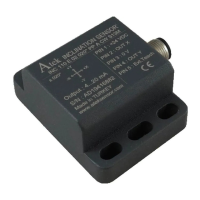
INC 110 E (Analog Output)
INC 110 series tilt sensors are used for inclination measurement for single (X) or two axes
(XY). They have ±90⁰ measurement range. These sensors with 0.1-10VDC voltage output or
4-20mA current output option, can take measure ment with ±0.1° accuracy. Thanks to its
compensated axis sensitivity, the effect of the axes on each other is minimized.
These sensors, especially used in machine and crane industries, can operate in outdoor
environments with their high IP protection classes.
sert ortamlarda açıları. Endüstride ve otomotiv mühendisliğinde her türlü uygulamada
kullanıma uygundur.
INCLINOMETER (TILT SENSOR) USER MANUAL
M12 - 5 PIN FEMALE
SOCKET
DETERMINING THE 0° POINT OF SENSOR
Pin 5 (pink cable) and pin 3 (black cable) are short-circuited once and then disconnected. Thus, the sensor recognizes
that the position is 0 °. If the same operation is repeated a second time, the sensor is reset to the factory settings.
During the operations, the sensor position should be kept constant for approximately 4 seconds.