

A
Ashley ThomasJul 26, 2025
What to do if there is no video from my ATEN Extender?
- AabrownJul 26, 2025
If you're experiencing a 'No video' issue with your ATEN Extender, ensure all cables are securely plugged into their respective sockets.
What to do if there is no video from my ATEN Extender?
If you're experiencing a 'No video' issue with your ATEN Extender, ensure all cables are securely plugged into their respective sockets.
Details FCC Class A compliance and potential interference.
Specifies intended use, environments, and RoHS/China compliance.
Provides URLs for product registration and online technical support.
Lists telephone numbers for technical support by region.
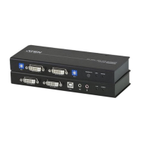
Lists items included in the CE700A USB KVM Extender package.
Advises reading the manual and handling procedures carefully.
Describes the extender's use, video quality, protection, and scenarios.
Outlines the simple connection process and integration with KVM switches.
Details distance, dual console, ESD/surge protection, gain control, resolution.
Mentions hot-pluggable, rack-mountable, and easy installation.
Specifies monitor, keyboard, mouse, and computer hardware needs.
Recommends cables and lists supported operating systems.
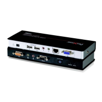
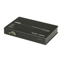
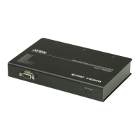
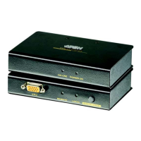
Identifies ports and indicators on the local unit's front panel.
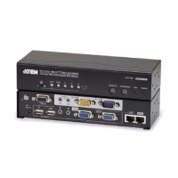
Identifies ports and indicators on the remote unit's front panel.
Details rear panel connectors like Console Ports, Power Jack, Remote I/O.
Identifies the grounding terminal on the side of the units.
Emphasizes turning off power before connecting devices.
Guides on mounting the CE700AL and CE700AR on system racks.
Explains the importance and method of grounding all devices.
Illustrates the grounding connection for units and peripherals.
Describes two methods for using STP cable shielding for grounding.
Details ensuring proper contact for grounding via RJ-45 connectors.
Guides connecting local console devices to the CE700AL.
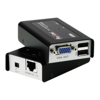
Details connecting the USB KVM cable to the local unit and computer.
Explains connecting Cat 5e cable between local and remote units.
Guides connecting power adapters to both units.
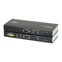
Illustrates rear connections for CE700AL and CE700AR.
Shows front connections and the link to the local PC.
Describes local console access with remote input disabled.
Explains simultaneous access, with waiting for active console.
Details remote console access when local console is idle.
Explains the meaning of Local and Remote LEDs on the local unit.
Explains the meaning of Link and Remote LEDs on the remote unit.
Lists types and quantities of connectors for CE700AL and CE700AR.
Details power consumption, video resolution, temp, and humidity.
Covers housing material, weight, and dimensions.
Illustrates the wiring configuration for TP cables.
Details the pin assignments for TP connectors.
Provides solutions for "No video" and "Poor video quality".
Explains the use of modified SPHD connectors for compatibility.
Outlines the vendor's liability and warranty terms for the product.
| PS/2 ports quantity | 0 |
|---|---|
| USB 2.0 ports quantity | USB 2.0 ports have a data transmission speed of 480 Mbps, and are backwards compatible with USB 1.1 ports. You can connect all kinds of peripheral devices to them. |
| Product color | Black |
| Maximum transfer distance | 150 m |
| Mounting kit | Yes |
| Cables included | KVM, USB |
| Harmonized System (HS) code | 84733020 |