3
GIRO
Abb./Fig. 5
D
Montage auf Rechteckrohr
Abb. 1
Befestigungsschrauben der hinteren Halteplatte lösen
(Abb. 1a). Fahrradträger provisorisch auf Grundträger aufsetzen
und hintere Halteplatte auf Tragrohrabstand ausrichten
(Abb.s1b). Dazu Schraube (A) in Haltebügel einschwenken und
Spannhebel umlegen (Abb. 1c). Befestigungsschrauben der
hinteren Halteplatte festziehen (ca. 6 Nm, Abb. 1d).
Abb. 2
Klemmbügel unter Tragrohr schwenken (Abb. 2a).
Schraube (A) in Klemmbügel einhängen (Abb. 2b).
Spannhebel umlegen (Abb. 2c).
Abb. 3
Durch Drehen des Spannhebels Klemmkraft einstellen.
Fahrradträger auf festen und sicheren Sitz überprüfen.
Spannhebel durch Abschließen sichern (Abb. 3a).
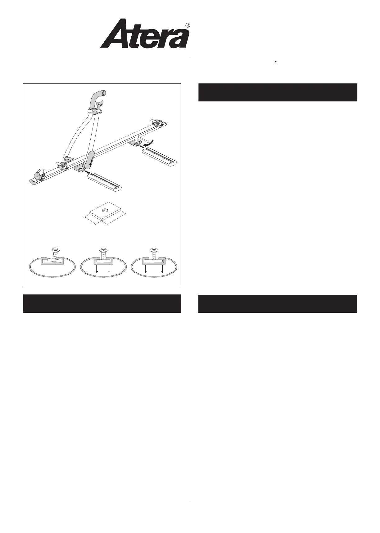
Montage auf Profilrohr
Abb. 4
Spannhebel und Klemmbügel gegen Nutenstein mit Schraube
(M6x12mm) austauschen.
Abb. 5
Fahrradträger in Profilrohr einschieben.
Schrauben handfest anziehen (ca. 6 Nm).
Installation on square bar
Fig. 1
Loosen the fastening screws of the rear holding plate (Fig 1a).
Position the bicycle carrier provisionally on the roof rack and
adjust the rear holding plate to the distance between the carrier
bars (Fig. 1b). To do this, insert the screw (A) into the holding
bracket and fold down the clamping lever (Fig. 1c). Tighten the
fastening screws of the rear holding plate (approx. 6 Nm,
Fig.1d).
Fig. 2
Swivel the clamping bracket underneath the carrier bar (Fig. 2a).
Insert the screw (A) into the clamping bracket (Fig. 2b). Fold
down the clamping lever (Fig. 2c).
Fig. 3
Turn the clamping lever to adjust the clamping force .
Check that the bicycle carrier is fastened firmly and securely.
Lock the clamping lever (Fig 3a).
Installation on profile bar
Fig. 4
Replace the clamping lever, screws and clamping brackets from
the front and rear holding plates and replace with srews
(M6x12mm)
and threaded plates.
Fig. 5
Insert the bicycle carrier into the profile bar. Tighten the screws
making sure they are hand-tight (approx. 6 Nm).
F
Montage sur tube rectangulaire
Fig. 1
Desserrer les vis de fixation de la plaque de support arrière
(fig.1a). Placer provisoirement le porte-vélo sur le support de
base et ajuster la plaque de support arrière à la distance des
tubes du porte-bagages (fig. 1b). Introduire à cet effet la vis (A)
dans l’étrier de retenue et rabattre le levier de serrage (fig. 1c).
Resserrer les vis de fixation de la plaque de support arrière
(env. 6 Nm, fig. 1d).
Fig. 2
Pivoter l’étrier de serrage au-dessous du tube (fig. 2a).
Introduire la vis (A) dans l’étrier de serrage (fig. 2b).
Rabattre le levier de serrage (fig. 2c).
Fig. 3
Tourner le levier de serrage pour régler l’effort de serrage .
Vérifier que le porte-vélo est serré à fond. Verrouiller le levier de
serrage (fig. 3a).
Montage sur tube profilé
Fig. 4
Remplacer le levier et l’étrier de serrage par un coulisseau avec
vis
(M6x12mm)
.
Fig. 5
Introduire le porte-vélo dans le tube profilé.
Serrer les vis à la main (env. 6 Nm).
a
b
Art.-Nr.
Art. no.
rticle:
82 21
✗
b
✔
a
✔
ca. 6Nm
 Loading...