Do you have a question about the AtGames LEGENDS PINBALL and is the answer not in the manual?
Lists the essential components included with the VIBS system for installation.
Details the necessary hardware and PC specifications for using the VIBS.
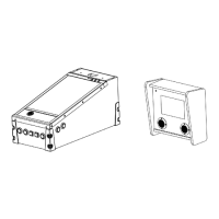
The main VIBS board for connecting PC to backglass display.
Cable used for connecting the VIBS board to the backglass screen.
Components for the user-configurable switch button.
Wiring harness connecting the microswitch to the VIBS board.
Connects EDP from mainboard and HDMI from PC for video signals.
EDP output port for connection to the Legends Pinball backglass screen.
Connector for the VIBS switch button for input selection.
Handle components with care and unplug power before installation.
Upright black bar indicates unlocked port for cable insertion/removal.
Flat black bar indicates locked port after cable connection.
Using finger or fingernail to operate the lock/unlock lever.
Unplug the Legends Pinball from the power outlet.
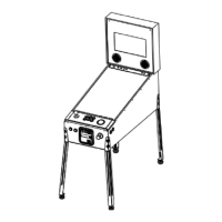
Remove backglass and lower panels for access.
Identify early or later production backglass connection types.
Match backbox wiring to Early Production picture.
Install VIBS between EDP cable junctions in the backbox.
Step-by-step guide to safely disconnect the EDP cable.
Visual confirmation of a disconnected EDP cable.
Remove backglass cable from the Signal Transfer Board.
Ensure the black bar on the Signal Transfer Board is unlocked.
Carefully remove the EDP cable from the Signal Transfer Board.
Ensure the EDP connector on the signal transfer board is unlocked.
Connect the EDP cable to the green Signal Transfer Board.
Confirmation that the cable is properly in place.
Tuck the Signal Transfer board into the lower compartment.
Slowly lower the feed cable and board until a few inches of EDP cable remain.
Unlock Port D on the VIBS board for connection.
Slide backbox EDP cable into VIBS Port D carefully.
Lock Port D by pushing down the black lever.
Unlock Port A on the VIBS board for connection.
Slide mainboard EDP cable into VIBS Port A carefully.
Lock Port A by pushing down the black lever.
Route wiring through the cabinet for button placement.
Install microswitch into button housing and feed through cabinet.
Choose desired location to mount the switch button.
Connect HDMI cable from PC to VIBS HDMI input.
Route HDMI cable to the lower body or directly to VIBS.
Use of HDMI right angle extension cable for easier wiring.
Connect PC backglass video stream via HDMI to VIBS.
Connect PC playfield video via HDMI to Legends Pinball top panel.
Connect PC USB OTG data cable to Legends Pinball top panel USB port.
Configure Legends Pinball settings for OTG mode.
Configure display output to the main playfield.
Adjust display orientation or rotation.
Verify PC screen is visible on the main playfield.
Use button to toggle between native and PC backglass video signals.
Address cycling colors or lost display detection.
Device care, water avoidance, heat, magnets, cleaning, and transformer usage.
| Manufacturer | AtGames |
|---|---|
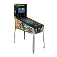
| Type | Virtual Pinball Machine |
| Backglass Display | 15.6-inch LCD |
| Audio | Stereo speakers with subwoofer |
| Weight | 150 lbs |
| Display | 32-inch LCD Playfield |
| Resolution | 1920 x 1080 |
| DMD Display | LCD |
| Storage | 16GB |
| Connectivity | Wi-Fi, Bluetooth |
| Games Included | 22 |
| Expandable Games | Yes |
| Haptics | Yes |
| Power Supply | 110-240V, 50/60Hz |