78
SL1 DATA LOGGER User Manual Rev. AD
sales.get@athena.euwww.getdata.it
ENGLISH
ANNEX 2 PINOUTS
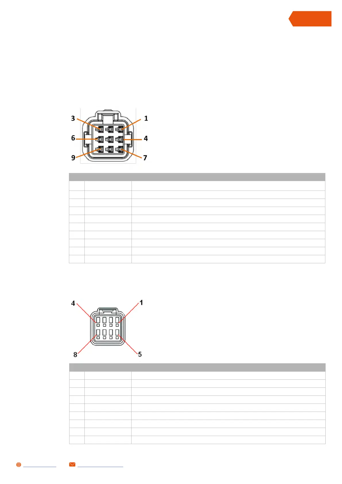
1 “MAIN” CONNECTOR
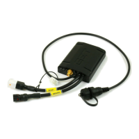
The following chapter shows the pinout for all connectors on the SL1 Data Logger
2 “EXP” CONNECTOR
MAIN CONNECTOR PINOUT
PIN SIGNAL NAME DESCRIPTION
1 VPWR Power supply positive
2 GNDPOW Power supply negative
3 CAN0L CAN Port GET - CANL signal
4 CAN0H CAN Port GET - CANH signal
5 GNDSEN Auxiliary power supply and analogue/frequency input negative
6 SL1TOE XT Reserved
7 E X T TOSL1 Reserved
8 IC1 Frequency input (0-12V)
9 BEACON Reserved
MAIN connector
Front view
(The wires exit from the rear)
EXP connector
Front view
(The wires exit from the rear)
EXP CONNECTOR PINOUT
PIN SIGNAL NAME DESCRIPTION
1 DO Digital output (only available for the new model)
2 GNDSEN Auxiliary power supply and analogue/frequency input negative
3 CAN1L CAN Port EXP - CANL signal
4 CAN1H CAN Port EXP - CANH signal
5 AN1 Analogue input 1 (0-5V)
6 5VAUX Auxiliary power supply output (5VDC)
7 AN2 Analogue input 2 (0-5V)
8 AN3 Analogue input 3 (0-5V)
 Loading...