GasSens Gas Detection System Section 2 - A14 Receiver Module
O & M Manual
A14-RK, 8/06 2 - 2
A1 A2 A3 TROUBLE
TB2
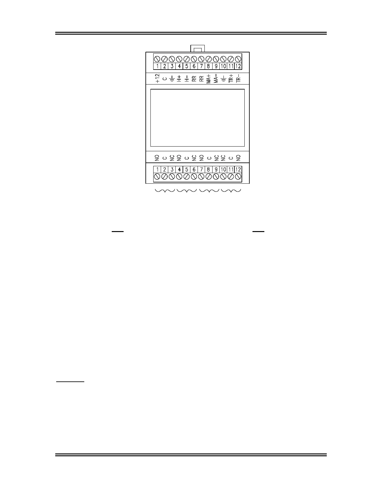
TB1 TB2
1: +12 Module Power positive (12 VDC) 1: A1 NO Alarm 1 normally open contact
2: C Module Power Common 2: A1 C Alarm 1 common
3: Earth Ground (REQUIRED) 3: A1 NC Alarm 1 normally closed contact
4: H+ Audible Horn positive 4: A2 NO Alarm 2 normally open contact
5: H- Audible Horn negative 5: A2 C Alarm 2 common
6: RR Remote Reset 6: A2 NC Alarm 2 normally closed contact
7: RR Remote Reset 7: A3 NO Alarm 3 normally open contact
8: MA+ 4-20 mA output positive 8: A3 C Alarm 3 common
9: MA- 4-20 ma output negative 9: A3 NC Alarm 3 normally closed contact
10: Earth Ground 10: TROUBLE NC trouble normally closed contact
11: TR Transmitter Input 11: TROUBLE C Trouble common
12: TR Transmitter Input 12: TROUBLE NO Trouble normally open contact
NOTE: Relay contact designation is shown for relays in normal mode of operation for relays A1,
A2 and A3. If fail-safe relay operation is selected, NO and NC designations are reversed
for that relay. The TROUBLE relay is set to fail-safe operation at the factory, and the
designation shown above is for the trouble relay in fail-safe mode.
Figure 2-2: Receiver Module Terminals (ATI-029)
CAUTION: Receiver modules MUST be connected to a secure earth ground. Terminal 3 of
TB1 in Figure 2-2 above must be connected to the earth ground terminal of
ATI's power supply module as shown in the connection diagram in Figure 1-3.
If the user is providing another 12 VDC supply, be sure that the receiver is
properly grounded.