Universal Power Supply Section 3 – A17 Power Supply Module
O & M Manual
A14-RK, 8/06 3- 2
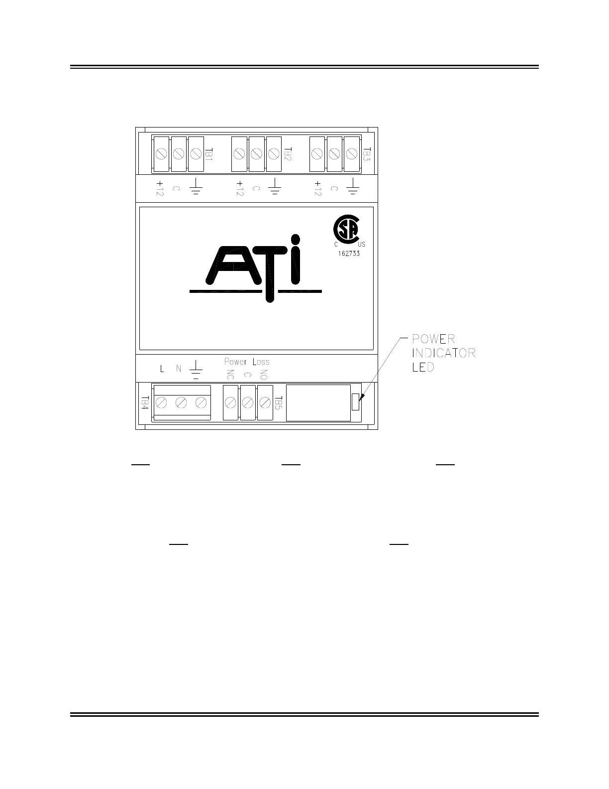
Figure 3-1 provides detailed information on the terminals provided on the power supply. All terminal
blocks are plug-in type, and can be easily unplugged should removal of the module be necessary.
Analytical Technology, Inc.
TB1 TB2 TB3
(12V Battery only)
1: +12 External Battery (+) 1: +12 Receiver Module (+) 1: +12 Receiver Module (+)
2: C External Battery (-) 2: C Receiver Module Common 2: C Receiver Module Common
3: Earth Ground 3: Earth Ground 3: Earth Ground
TB4 TB5
1: L AC power hot (85-255 VAC) 1: NC Power failure normally closed contact
2: N AC power neutral 2: C Power failure common
3: AC power ground (earth ground REQUIRED) 3: NO Power failure normally open contact
NOTE: AC power input must be properly earth grounded for safe operation. 220 VAC power without a
neutral line may not be used with this power supply.
Figure 3-1: Power Supply Terminal Connections (ATI-030)