RADEON™ 8500/ RADEON 7500™ User’s Guide 5
RADEON 8500/RADEON 7500 Display
Configurations
Legend:
CRT-(cathode ray tube) analog monitor utilizing the standard 15-pin VGA connector
DFP-digital flat panel monitor utilizing the 24-pin DVI-I connector
- The DVI-I connector can support a monitor using a 15-pin VGA connector via
DVI-I-to-VGA adapter
- The s-video connector on the board can support a composite connector via
s-video-to-composite adapter
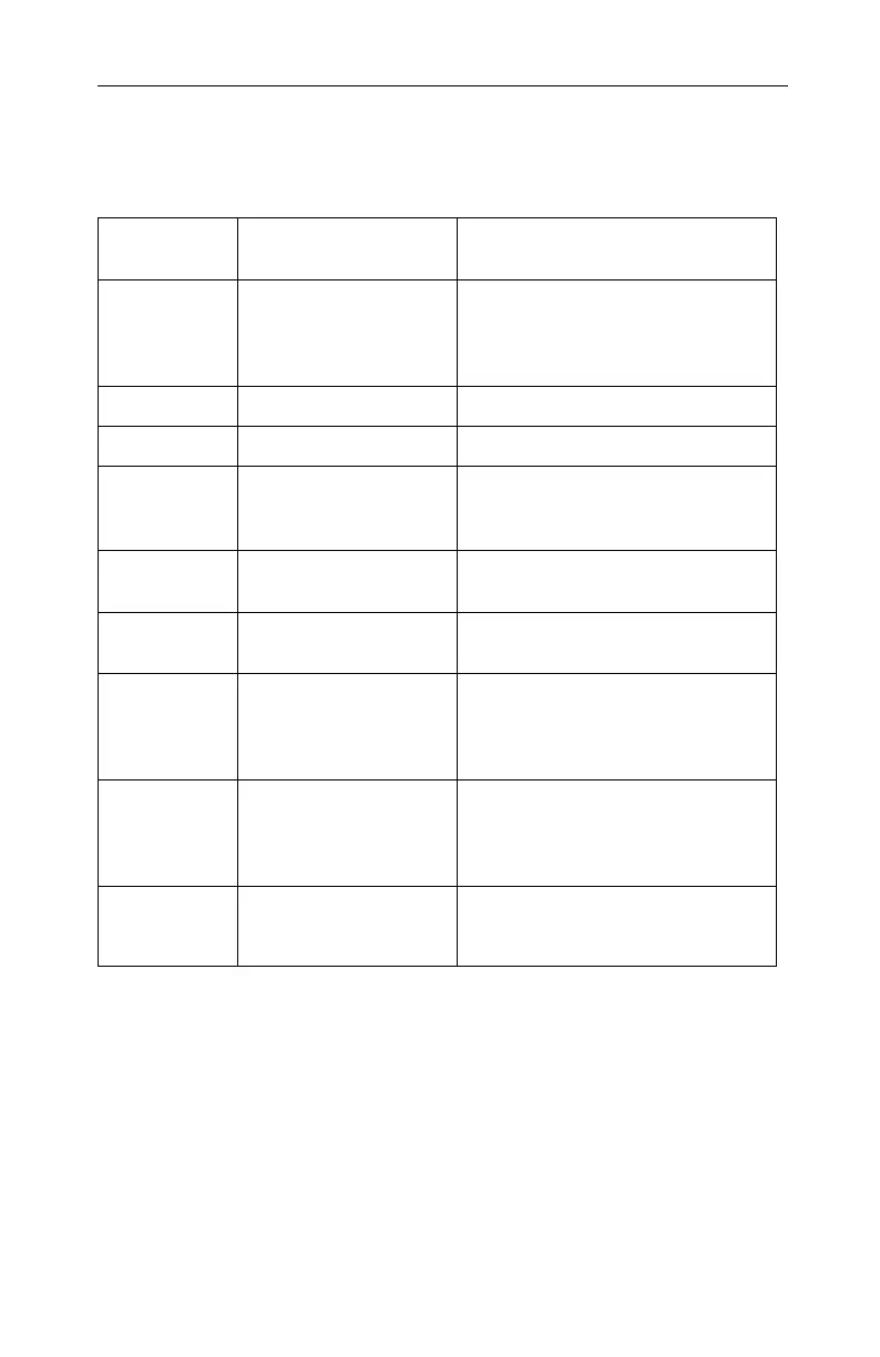
Display
Configuration
Connector(s) Used Comments
CRT monitor - 15-pin VGA connector
- 24-pin DVI-I connector
(with DVI-I-to-VGA
adapter)
DFP monitor - 24-pin DVI-I connector
TV - s-video connector
CRT monitor +
TV
- 15-pin VGA connector +
s-video connector
Unsupported configuration if the CRT
monitor is attached to DVI-I connector
via DVI-I-to-VGA adapter
DFP monitor +
TV
- 24-pin DVI-I connector +
s-video connector
CRT monitor +
DFP connector
- 15-pin VGA connector +
24-pin DVI-I connector
CRT monitor +
CRT monitor
- 15-pin VGA connector +
24-pin DVI-I connector
(with DVI-I-to-VGA
adapter)
CRT monitor +
DFP monitor +
TV
- 15-pin VGA connector +
24-pin DVI-I connector +
s-video connector
Please note that this will result in two
independent displays with the third
display “cloning” the image of one of the
other two displays.
CRT monitor +
CRT monitor +
TV
UNSUPPORTED
CONFIGURATION