U0594061-DPage 20 / 82 CORFIRST / CORSUN 2 / CORFLOW
EN
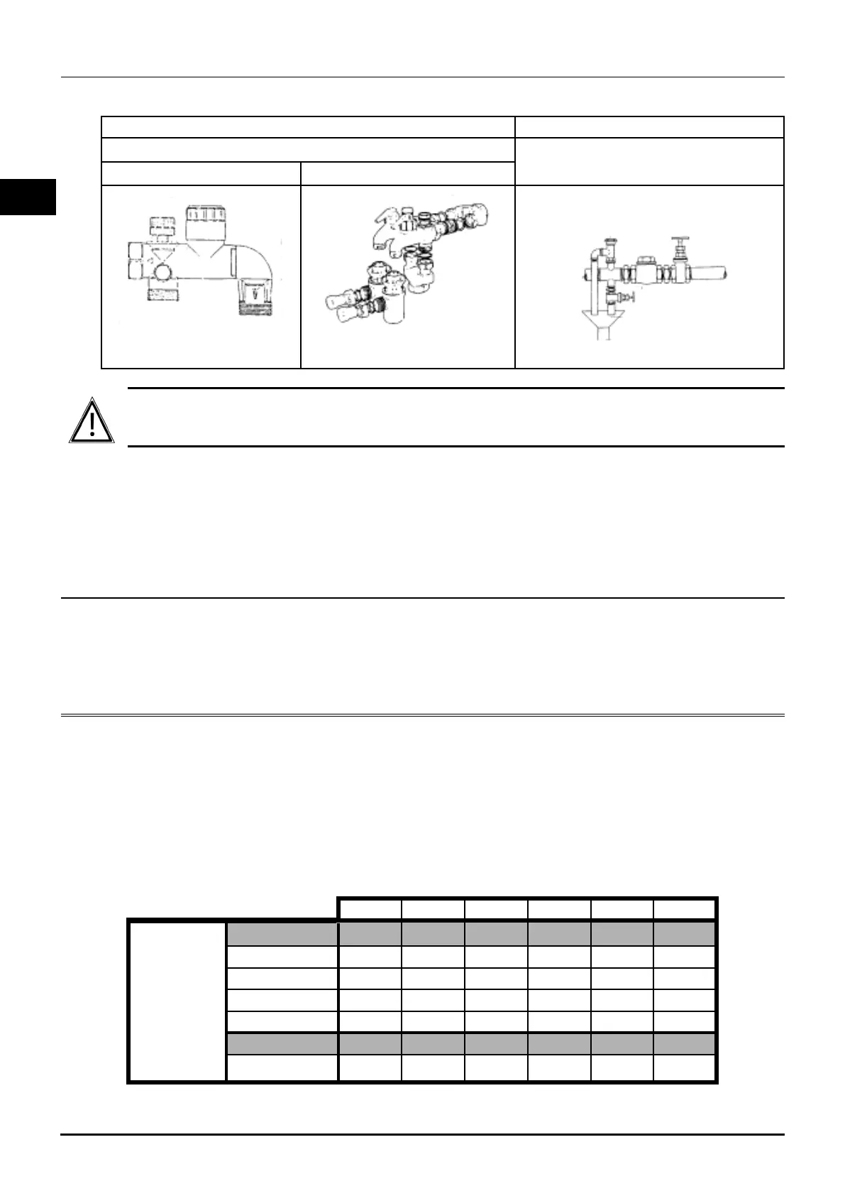
5.3.2. Safety valves:
The safety valves are tted to the tank inlet using a T (see diagram below).
SAFETY UNIT SAFETY VALVE
On cold water inlet only
On tank inlet
1 single G 1¨ unit 1¼¨ kit with 2 G 1¨ units
Valve diameter ≥
tank connector diameter
Safety valve/non-return ap/valve
A non-return ap preceded by a valve must be tted to the cold water inlet if the tank is
equipped with a safety valve. To avoid scaling of these components, operate the safety unit
at least once a month by moving its controls to various positions.
No non-return valve or ap should ever be tted between the safety valve or safety unit
and the tank.
5.4. Hydraulic connection diagram
See Appendix A page 63.
6. ELECTRIC ELEMENTS
Tank heating time with resistor(s):
These estimated heating times are given for storage at 60°C and cold water at 10°C.
On CORFIRST and CORFLOW Shielded option
It is possible to add 5 to 30 kW shielded resistors, according to the following recommended
combinations.
500 750 900 1000 1500 2000
CORFIRST
Heated volume 248 378 441 463 630 755
5 kW 3:00 4:30 5:15 5:15 7:15 8:45
10 kW 1:30 2:15 2:30 2:30 3:45 4:30
15 kW - 1:30 1:45 1:45 2:30 3:00
25 kW - 0:45 1:00 1:00 1:30 1:45
Heated volume 199 301 364 385 506 562
30 kW 0:25 0:35 0:45 0:45 1:00 1:05