2
Scupper
Maximum Falls
Height Above Basin
Flow Rate
SS12 / CS12 24” 1200 GPH
SS24 / CS24 30” 2400 GPH
SS36 / CS36 36” 3600 GPH
Introduction
Thank you for choosing Atlantic’s Stainless Steel and/or Copper Finished Spillway Scuppers.
All Atlantic Scuppers are constructed of 304 stainless steel. Copper nished scuppers have an
additional antique copper plating over the stainless steel for a warm traditional look.
Installation Requirements
• Atlantic Spillway Scuppers are constructed of 304 stainless steel are intended for fresh water
use only. Use with Chlorinated pool water or other acidic additives may cause the stainless
steel to discolor.
• Spillway Scuppers are designed for use in Pond-free and fountain applications. Scuppers are
not intended for use in water gardens or any pond with plant or aquatic life.
• Atlantic Spillway Scupper can support 80lbs. per linear foot of evenly distributed weight over
the top of the Scupper. (Ex. A 24” Scupper can support 160 lbs.) If the weight of the wall stone
and caps above the scupper exceeds the recommended weights limits a lintel must be installed
above the scupper to carry the excess load.
• Atlantic Scuppers are designed to easily install in dry stack garden walls utilizing a standard
4”H x 8”W x 12”L wall block. Although any sized wall block can be used, a 4 x 8 x 12 is ideal as
it requires very little alteration when installing the scupper.
Installation
The opening in the wall where the Scupper will be placed is important to the function of the
scupper. The bottom of the scupper must sit on a at surface and be fully supported for its entire
length. The scupper must be level side to side and front to back to for proper water ow.
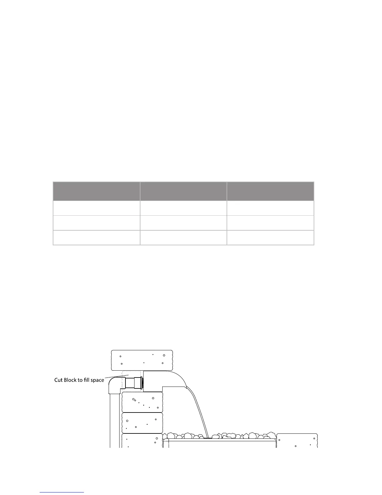
Installation in a garden wall using 4”H x 8”W x 12”L garden stones is easy because the scupper is
also 4” tall. Simply remove the necessary number of wall stones (one, two or three) from the top
course of the garden wall and replace them with the Scupper. The scupper should be positioned
so that the front of the body is even with the front of the wall. Cut 4” x 4” x 12” ller blocks to
complete the wall course and ll the area behind the scupper, leaving a 2 1/2” wide opening in
the center to connect the supply line. The scupper is load bearing (80 lbs. per linear foot max) so
caps can be placed on top of the Scupper to complete the installation.
Caution: Be sure to leave access to the scupper in case future maintenance is required. Do not
glue or permanently mortar the cap stones that are placed directly over the scupper.
and support wall caps
 Loading...