20/06/2011 PM 9845 0512 02 Page 10 of 36
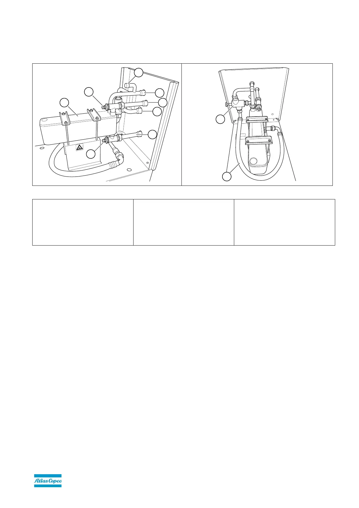
5.4. Main parts of the Energy Recovery unit
11-315 kW range (& VSD)
Figure 1
1. Water inlet connection
2. Water outlet connection
3. Temperature sensor, water out
4. Temperature sensor, water in
5. Oil inlet connection
6. Oil outlet connection
7. 1
st
bypass valve with thermostat
and lever for manual on/off control
of the ER unit
8. Heat exchanger (or ER unit)
9. Oil flexible (oil outlet)
10. Venting nipple
The functions of the main components are detailed below in this manual.
The size of the heat exchanger varies according to its range. The 55-90 kW range heat exchanger is shown in the figure
above. The set up is similar for other ER kits.
 Loading...