20/06/2011 PM 9845 0512 02 Page 13 of 36
30
+
-45 kW range (& VSD)
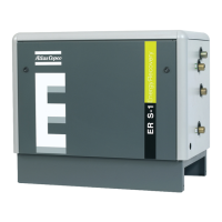
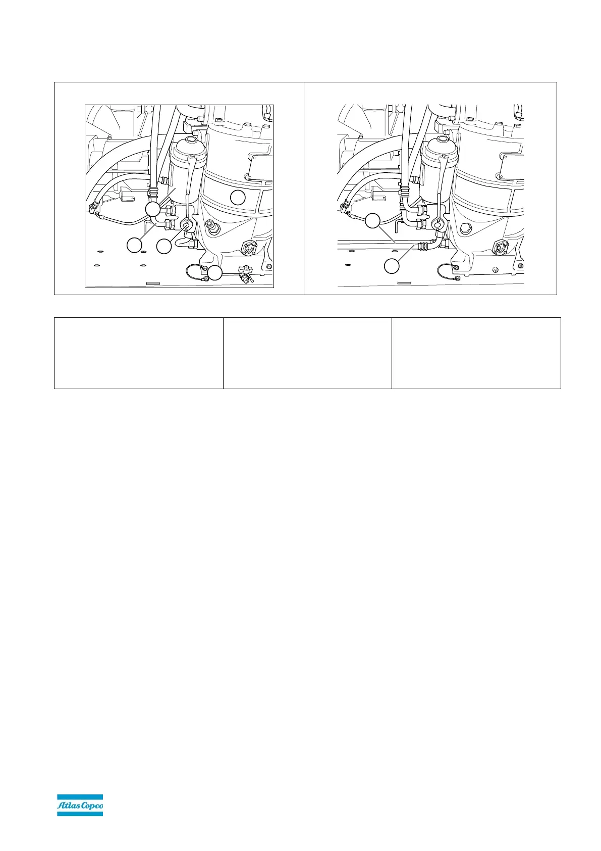
Figure 4: Modifications to vessel & oil filter pipe/housing to install the ER unit on 30
+
-45 kW (& VSD)
Before modifications
After modifications
10. Oil pipe (from vessel to oil inlet oil
filter pipe)
11. Oil drain
12. Oil separator vessel
13. Oil filter pipe with 2
nd
bypass valve
and oil filter housing
14. 2
nd
bypass valve (BV2) of filter pipe
15. Oil flexible (from vessel to oil inlet
connection of ER unit)
16. Oil flexible (from oil outlet
connection of ER unit to oil filter
pipe)
To allow the energy recovery unit to be inserted into the compressor oil circuit, the oil pipe (Figure 4-10) between the oil
separator vessel (Figure 4-12) and the oil filter housing (Figure 4-13) must be removed. This pipe will NOT be reused and
may be discarded.
The oil inlet and outlet pipes of the ER unit are provided with a hose nipple to connect the oil hose assemblies.
 Loading...