2920 1390 02
6
Instruction book
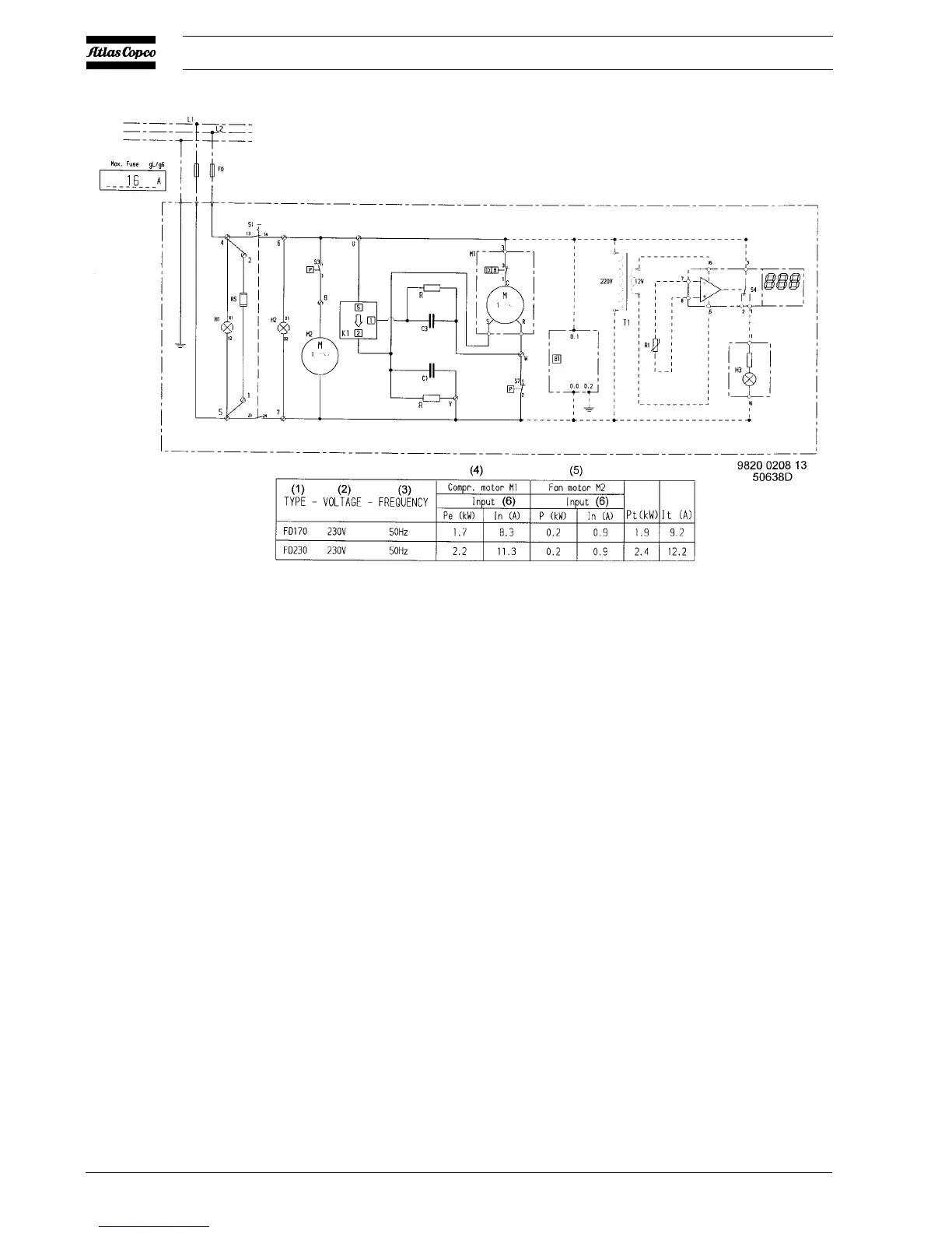
B1. Electronic condensate drain
(optional)
C1. Run capacitor
C3. Start capacitor
F0. Main fuses, local installation
(customer's installation)
H1. Indicator lamp, VOLTAGE ON
H2. Indicator lamp, DRYER RUN
H3. Indicator lamp, DEWPOINT
ALARM (optional)
K1. Start relay
M1. Compressor motor
M2. Condenser fan motor
R1. Temperature sensor, dewpoint
(optional)
RS. Crankcase heater
S1. Button, ON-OFF
S3. Fan control switch
S4. Electronic thermostat with
display (optional)
S7. High pressure shut down switch
T1. Transformer (optional)
Fig. 1.4 Electrical diagram of FD170 50Hz and FD230 50Hz
F0. Main fuses, local installation
(customer's installation)
F3/4. Fuses
F8. Thermal overload, fan motor
H1. Indicator lamp, VOLTAGE ON
H2. Indicator lamp, DRYER RUN
H3. Indicator lamp, DEWPOINT
ALARM (optional)
K1. Contactor, compressor motor
K2. Contactor, fan motor
M1. Compressor motor
M2. Condenser fan motor
Q1. Circuit breaker
Q2. Circuit breaker
R1. Temperature sensor, dewpoint
(optional)
RS. Crankcase heater
S0. Main switch (customer's
installation)
S1. Button, ON-OFF
S2. High pressure shut down switch
S3. Fan control switch
S4. Electronic thermostat with
display (optional)
T1. Transformer (optional)
1x1. Terminal strip
1x2. Terminal strip
Figs. 1.5 and 1.6
 Loading...