5. Installation
5.1. Installation proposal
Note:
Installation drawing of standard drawing is shown.
The vacuum pump must be installed on a level horizontal floor.
Use correct process pipe sizes to prevent restrictions and pressure drops.
Ambient and inlet temperature must not exceed the limits of the pump's working
range.
All dimensions given are in mm (inch).
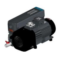
Figure 29 Installation proposal - GVS 16A and GVS 25A
A. Space for motor ventilation B. Space for exhaust filter exchangeA. Space for motor ventilation B. Space for exhaust filter exchange
12/2021 - ©Atlas CopcoPage 476996022430_C
Installation
 Loading...