LFx with CDXF air dryer
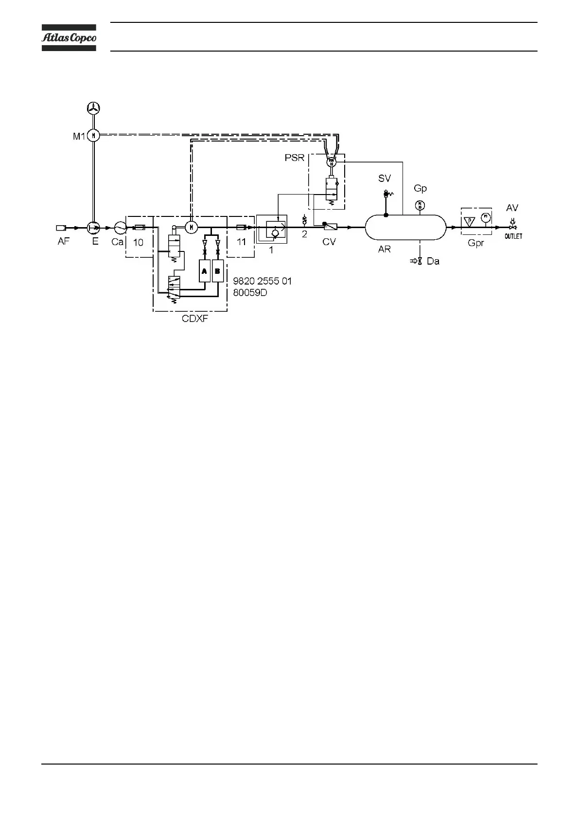
Flow diagram
When the ON/OFF switch is put to position ON and the pressure in the air receiver is low enough, pressure
switch (PR) starts the motor.
On single-phase LFx 1.5 and LFx 2.0 units a vent valve (2) ensures smooth start-up.
Air drawn through filter (AF) into compressor element (E) is compressed. The air is cooled in air cooler (Ca),
flows through the pre-filter and enters the CDXF dryer. Via the after filter and check valve (CV) the air enters
air receiver (AR) and is discharged via outlet valve (AV).
When the pressure in the air receiver reaches the upper limit, pressure switch (PR) stops the motor.
On LFx 1.5 and LFx 2.0 units a quick blow-off valve (1) blows off the air between element (E) and check
valve (CV) and ensures smooth stopping.
The air receiver is equipped with a manual drain (Da) for draining the condensate after stopping.
Instruction book
14 2920 7002 03
 Loading...