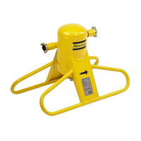
The Atlas Copco OSC 145 is a condensate treatment device designed to separate oil from oil-containing condensate produced by oil-injected compressors. This process ensures that the condensate meets environmental codes before disposal. The OSC 145 is a two-step unit, meaning it has two towers for the oil separation process.
Function Description:
Compressed air from oil-injected compressors contains a small amount of oil. When this air is cooled in the aftercooler and refrigeration dryer, oil-containing condensate is formed. The OSC 145 is specifically designed to treat this condensate by separating the majority of the oil using filters. The device is built to be insensitive to shocks and vibrations, making it suitable for use with various types of drains.
The condensate, containing fine oil droplets, enters the unit through mufflers, where it is depressurized. It then flows into the first tower and seeps through an oleophilic filter. This filter is designed to absorb most of the oil present in the condensate. The oleophilic filter floats on the water, and as it absorbs more oil, it sinks deeper. A service indicator moves downwards with the filter, signaling when it needs to be replaced.
After passing through the first tower, the water, which still contains a small quantity of oil, gradually flows to a second tower. In this second tower, an activated carbon filter is installed. This filter absorbs almost all of the remaining oil, ensuring that the discharged condensate is clean. The clean condensate is then drained to the condensate outlet.
Important Technical Specifications:
The model designation "OSC 145" indicates the air capacity of the compressor in liters per second. For the OSC 145, the dimensions are:
- A (mm): 680
- B (mm): 255
- C (mm): 940
- Shipping weight (kg): 15
- Operating weight (kg): 53
Connections:
The OSC 145 offers multiple inlet and outlet connection options in BSP/NPT:
- Inlet: 1 x 1/2", 2 x 1/2", 2 x 3/4"
- Outlet: 1 x 1/2", 1 x 3/4", 1 x 1"
Reference Conditions and Limitations:
- Effective working pressure of the compressor: 7 bar(e)
- Compressor running hours per day: 12 hours
- Oil type: Roto-Inject Fluid, Roto-Xtend Duty Fluid, Roto-Foodgrade Fluid
- Compressor type: All types of GA oil injected compressors
Climate types for reference conditions:
- Cold climate: Ambient temperature of 15 °C (59 °F) and relative humidity of 60%
- Mild climate: Ambient temperature of 25 °C (77 °F) and relative humidity of 60%
- Hot climate: Ambient temperature of 35 °C (95 °F) and relative humidity of 70%
Limitations for operation:
- Minimum inlet temperature: 1 °C
- Minimum ambient temperature: 1 °C
- Maximum condensate inlet temperature: 75 °C
- Maximum oil content at outlet of the OSC: 15 mg/l
- Maximum oil flow rate: 10.5 g/h (0.37 oz/h)
Compressor FAD (Free Air Delivery) capacity for OSC 145:
- Cold climate: 270 l/s
- Mild climate: 145 l/s
- Hot climate: 70 l/s
For poly-glycol based condensates, the capacity of each unit should be halved.
Correction factors for running hours per day (for operation in other than reference conditions, multiply the compressor capacity with the appropriate correction factor):
- 8 hours/day: 1.50
- 10 hours/day: 1.20
- 12 hours/day: 1.00
- 14 hours/day: 0.86
- 16 hours/day: 0.75
- 18 hours/day: 0.67
- 20 hours/day: 0.60
- 22 hours/day: 0.55
- 24 hours/day: 0.50
Separation performance: For an outlet oil carry-over of 10 mg/l instead of 15 mg/l, the unit capacity should be multiplied by 2/3.
Usage Features:
- Installation: The OSC 145 should be installed on a level floor capable of supporting its weight. Sufficient free space must be reserved for filter replacement. The unit must be positioned higher than the sewer, and the outlet piping should have a slight downward slope to the sewer to ensure proper flow without pressure buildup. The outlet piping should have an inner diameter of at least 19 mm (3/4").
- Condensate Inlet: The automatic drain of the compressor condensate trap connects to one or both condensate inlets of the OSC. The piping diameter must be at least 6 mm and laid out to avoid pockets where condensate can collect.
- Commissioning: Before putting into operation, the plastic bags around the filters must be removed (but not the net). The activated carbon filter in the second tower must be placed on the flow plate and checked to ensure it doesn't float. Clean water is poured into the unit until it comes out of the condensate outlet. The oleophilic filter is then placed on the water surface in the first tower without being pushed down.
- Safety: The device should be placed in a cool, clean area, free of flammable fumes, vapors, and particles. Electrical connections must comply with codes, and the device must be earthed and protected against short circuits. A lockable power isolating switch should be installed nearby. Safety precautions during installation, operation, and maintenance must always be followed, including stopping and de-energizing machines before any intervention.
Maintenance Features:
- Regular Checks: Filters must be checked regularly to prevent untreated condensate from entering the sewer. Condensate samples should be collected weekly using the test valve and compared to a 15 ppm turbidity reference bottle.
- Oleophilic Filter Replacement: The oleophilic filter needs replacement when its service indicator approaches the lid of the tower. The lifetime of the filter depends on the amount of oil in the condensate. During replacement, the compressor must be stopped, de-energized, and the outlet piping depressurized. The old filter is removed, and a new one (white label) is fitted, ensuring it's not pushed below the water surface. The inside of the OSC can be cleaned with water and tissue if necessary, but no soap or detergents should be used as they can break oil/water emulsions.
- Activated Carbon Filter Replacement: Activated carbon filters must be replaced when the oleophilic filters are changed for the second time, when the filters get clogged, or when the condensate from the test outlet is less transparent than the reference glass. Similar to oleophilic filter replacement, the compressor must be stopped and depressurized. The old activated carbon filter is removed, and a new one (black label) is fitted, observing its correct position. The vessels should be cleaned with water and tissue (no soap/detergents). The unit is then refilled with clean water until it comes out of the condensate outlet.
- Service Kits: Atlas Copco offers service kits for maintenance, comprising genuine parts.
- Service kit A (Part No. 2901 1402 00): Contains 1 oleophilic filter, 1 diffuser, and 1 muffler. For the first service after installation when condensate is normal.
- Service kit B (Part No. 2901 1402 01): Contains 2 oleophilic filters, 1 activated carbon filter, 2 diffusers, and 2 mufflers. For changing oleophilic filters twice and activated carbon filters once, when condensate is normal.
- Service kit D (Part No. 2901 1577 00): Contains 1 oleophilic filter, 1 activated carbon filter, 1 diffuser, and 1 muffler. For when condensate contains a lot of oil, saturating all filters simultaneously.
- Spare Parts: Individual spare parts like lids, ball valves, and reference glass are available.
- Disposal: Used filters and other materials must be disposed of in an environmentally friendly and safe manner, in accordance with local regulations.
- Problem Solving: The manual provides guidance for common issues such as excessive oil entering the OSC, rising service indicator (indicating too much condensate), or a clogged unit. Remedies include replacing filters, cleaning vessels, and checking compressor FAD.
Options:
- Alarm (Part No. 8092 2849 29): Optional electronic alarm sensors are available to warn the operator of condensate overflow and filter replacement.
- Manifold (Part No. 8070 2167 03): An optional manifold is available for easy connection of several condensate lines into the unit.
- Anti-bacteria kit (Part No. 8092 2850 17): An optional kit to prevent the growth of bacteria in the unit.
- Anti-freezing kit (Part No. 8092 2848 95): An optional heater kit to prevent the condensate from freezing.