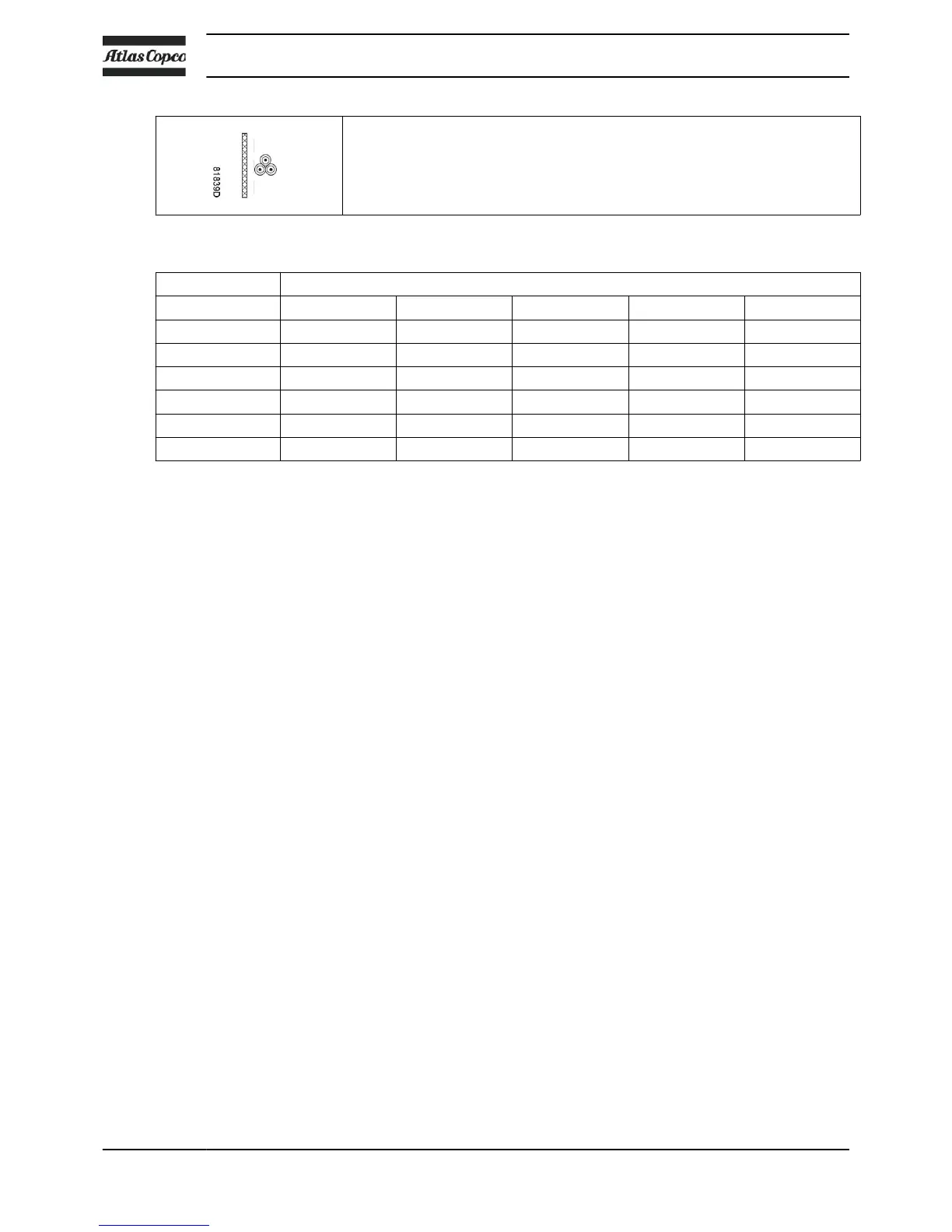
Installation method F according table B.52.1.
Single-core cables, touching in free air
Clearance to wall not less than one cable diameter
Maximum allowed current in function of the ambient temperature for installation method F
Ambient temperature
Cable section 30 °C 40 °C 45 °C 50 °C 55 °C
25 mm² < 110 A < 96 A < 87 A < 78 A < 67 A
35 mm² < 137 A < 119 A < 108 A < 97 A < 84 A
50 mm² < 167 A < 145 A < 132 A < 119 A < 102 A
70 mm² < 216 A < 188 A < 171 A < 153 A < 132 A
95 mm² < 264 A < 230 A < 209 A < 187 A < 161 A
120 mm² < 308 A < 268 A < 243 A < 219 A < 188 A
Calculation method for IEC:
•
Single supply cables (3 phases + PE - configuration (1)):
• Add 10 % to the total current (I
tot
from the tables)
• Install the prescribed fuse on each cable
• Parallel supply cable (2 x 3 phases + PE - configuration (2)):
• Add 10 % to the total current (I
tot
from the tables) and divide by 2
• Multiply the ampacity of the cables with 0.8 (see table A.52.17 (52-E1))
• Install fuses of half the size of the recommended maximum fuse size on each cable.
• When using 2 x 3 phases + PE as in (3):
• Add 10 % to the total current (I
tot
from the tables) and divide by √3
• Multiply the ampacity of the cables with 0.8 (see table A.52.17 (52-E1))
• Fuse size: the recommended maximum fuse size divided by √3 on each cable.
• Size of the PE cable: use following rule of thumb:
• For supply cables up to 16 mm²: same size as supply wires
• For supply cables between 16 mm² and 35 mm²: 16 mm²
• For supply cables larger than 35 mm²: half the size of the supply wires
Always check the voltage drop over the cable (less than 5 % of the nominal voltage is
recommended)!
Example: For SF 22 FF 400 V 50 Hz IEC, I
tot
= 52 A, ambient temperature is 40 °C,
recommended fuse: maximum 63 A.
• In case of single supply cables (3 phases + PE - configuration (1)):
• I = 52 A + 10 % = 52 x 1.1 = 57.2 A
• The table for installation method B2 allows a maximum current of 54 A for a 16 mm²
cable. For a cable of 25 mm², the maximum allowed current is 70 A, which is sufficient.
Therefore, use a 3 x 25 mm² + 16 mm² cable.
If method C is used, 16 mm² is sufficient (maximum 66 A at 40 °C). Use a 3 x 16 + 16
mm² cable.
• Install 63 A fuses.
• In case of parallel supply cables (2 x 3 phases + PE - configuration (2)):
• I = (52 A + 10 %)/2 = (52 x 1.1)/2 = 28.6 A
Instruction book
100 2920 7140 52
 Loading...