Do you have a question about the Atlas Radio Atlas 180 and is the answer not in the manual?
| Brand | Atlas Radio |
|---|---|
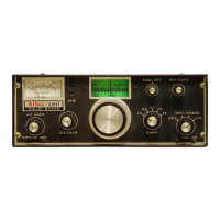
| Model | Atlas 180 |
| Category | Transceiver |
| Language | English |
Details frequency bands and tuning methods.
Highlights receiver sensitivity, selectivity, and performance.
Details broadband design and power output.
Explains emission types, keying, and transmit controls.
Explains the receiver's no-preamplification design and sensitivity.
Details crystal filter selectivity and unique oscillator switching.
Advises on precautions and DC power connection.
Discusses common automotive noise and suppression methods.
Shows mounting options and DC cable connection.
Recommends installing a fuse near the battery for safety.
Details microphone types and VOX activation.
Details rear panel layout and auxiliary socket pinout.
Explains power switches, mode selection, and gain controls.
Explains band selection and SSB tuning techniques.
Details tuning knob, PA bias, and calibrator adjustments.
Details PTT/VOX operation and modulation level adjustment.
Explains CW mode, keying, and frequency shift.
Discusses SWR, impedance matching, and antenna tuners.
Provides step-by-step instructions for SWR measurement.
Highlights mobile antenna tuning and impedance matching.
Explains ALC function and linear amplifier ALC connection.
Details DC power cable connection and polarity protection.
Explains voltage symbols, RMS, and measurement conditions.
Lists voltage readings for various plug-in boards.
