3/12
AtlasSound.com
TELEPHONE: (800) 876-3333
FAX: (800) 765-3435
©2014 Atlas Sound L.P. All rights reserved. Atlas Sound is a trademark of Atlas Sound L.P. All other trademarks are the property of their respective owners. All specs are subject to change without notice. ATS004327 P/N 491548 RevB 9/14
100, 200, 500, 700, & FMA Series
Floor-Standing Cabinets
1601 JACK MCKAY BLVD.
ENNIS, TEXAS 75119 U.S.A.
4. Shipping Packaging Removable
CAUTION: Ensure adequate manpower is available to help safely unload and install the system. Empty cabinets alone may weigh up to 200 lbs.
Moving rack cabinets can present dangers to both personnel and installed equipment.
CAUTION: Use eye protection and protective gloves while unpacking and installing the cabinet.
a. The cabinet will be shipped on a wood pallet. Select an unpacking location with adequate surrounding space for the unloading process.
In addition, plan a smooth and unobstructed route to the installation site. Low obstructions, narrow pathways, doorsills, carpet, etc. can
hinder movement. Use care when navigating obstacles. Always push from the cabinet front or back surfaces, never pull a cabinet or push
from the cabinet sides.
b. Carefully cut and remove shipping straps holding cabinet to shipping pallet.
c. Remove shrink plastic and shipping materials.
d. Remove metal shipping stiffeners (up to 2 per cabinet depending on model) using a #2 Phillips screwdriver by removing the (4) 10-32 Phillips
cross-drive screws.
DID YOU KNOW? The Shipping stiffener is actually a standard 3RU panel; therefore, may be
repurposed to another location on the cabinet.
e. Carefully cut and remove the hardware bag containing door keys, rack rail hardware, top
hardware and set aside for future use.
5. Cabinet Orientation
a. The front of the cabinet is denoted by the presence of the Atlas Sound Logo plug
(top left on most models)
DID YOU KNOW? The Atlas Sound logo plug may be removed and replaced by Atlas Sound M-1A IR
Repeater in cases where a door blocks IR remote control signals.
b. Bottom of the cabinet will contain mounting points for casters.
c. Most cabinets are also sold with an installed flush rear door.
6. Initial Rail Setup
NOTE: 100 Series cabinets contain fixed rails and do not require any adjustments; therefore, 100
Series users may skip this section.
a. Adjustable rails may move forward and backward within the hat-section slot. In addition, there
is some adjustment up and down. Once rails are located as required, use
3
⁄8" hex socket driver
to torque into place. Recommended torque: 82 ± 2 in-lbs.
b. Locate front rails in the front-to-back direction as required by equipment to be installed. Once
located, be sure to leave an equal gap at the top and bottom of each rail as required to clear
any caster and/or mounting hardware.
NOTE: While front rails are typically mounted fully forward in the cabinet, this position may not provide
adequate clearance when front doors (purchased separately) are installed. Always consider the forward
space for knobs, connections, etc. as required by the installed components.
c. If equipped with rear rack rails (presence varies with product or may be purchased separately),
use a tape measure to locate rear rail within respect to the front rail surface. This distance will
vary with racked gear requirements. Again, be sure to leave an equal gap at the top and
bottom of each rail to clear any caster and/or mounting hardware.
NOTE: If the flush rear door (typical on most cabinets) is to be used, verify rear door lock will not
interfere with racked equipment.
d. Once rails are located as required, use
3
⁄8" hex socket driver to torque into place. Recommended torque: 82 ± 2 in-lbs.
1. Required Tooling:
a. Razor Knife
b. #2 Philips Cross-Drive Screw Driver (Manual or Auto)
c. 3/8” Hex Socket Driver
d. Tape Measure (optional)
2. Shipping Packaging Removable:
a. Carefully cut and remove shipping straps holding cabinet to shipping pallet.
b. Remove shrink plastic and shipping materials.
c. Remove metal shipping stiffeners (up to 2 per cabinet depending on model) by removing the (4) 10-32 philips cross-drive
screws. Use a #2 philips screwdriver for this task.
NOTE: Shipping stiffeners are actually a standard 3RU panel; therefore, may be used to help close the top of
the cabinet. Additional panels will be required to fully close the surface.
d. Carefully cut and remove the hardware bag containing door keys, rack rail hardware, top hardware. Keep for future use.
3. Cabinet Orientation:
a. The front of the cabinet is denoted by the presence of the Atlas Sound
Logo plug (top left on most models)
NOTE: Logo may be removed and replaced by M-1A IR
Repeater in cases where a door blocks IR remote control
signals.
b. Bottom of the cabinet will contain mounting points for casters.
4.
Initial Rail Setup:
NOTE: 100 Series cabinets do not require any adjustments;
therefore, 100 Series users may skip this section.
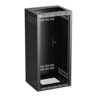
Logo Plug
Shipping
Stiffener
Caster Mount
Holes
a. Adjustable rails may move forward and backward within the hat-section
slot. In addition, there is some adjustment up and down. Once rails are
located as required, use 3/8” hex socket driver to torque into place.
Recommended torque: 82 ± 2 in-lbs
b. Locate front rails in the front-to-back direction as required by equipment
to be racked. Once located, be sure to leave an equal gap at the top and
bottom of each rail.
NOTE: While front rails are typically mounted fully forward in
the cabinet, this position may not provide adequate clearance
when accessory doors (purchased separately) are added.
Always consider the forward space for knobs, connections,
etc. as required by the installed components.
¼-20 Hex Bolt for
Rail Adjustment
c. If equipped with rear rack rails, use tape measure to locate rear rail
within respect to the front rail surface. This distance will vary with racked
gear requirements. Again, be sure to leave an equal gap at the top and
bottom of each rail.
NOTE: If the flush rear door (typical on most cabinets) is to be
used, verify rear door lock will not interfere with racked
equipment.
d. Once rails are located as required, use 3/8” hex socket driver to torque
into place. Recommended torque: 82 ± 2 in-lbs.
P/N 491548 Rev A
1
⁄4-20 Hex Bolt for
Rail Adjustments
1. Required Tooling:
a. Razor Knife
b. #2 Philips Cross-Drive Screw Driver (Manual or Auto)
c. 3/8” Hex Socket Driver
d. Tape Measure (optional)
2. Shipping Packaging Removable:
a. Carefully cut and remove shipping straps holding cabinet to shipping pallet.
b. Remove shrink plastic and shipping materials.
c. Remove metal shipping stiffeners (up to 2 per cabinet depending on model) by removing the (4) 10-32 philips cross-drive
screws. Use a #2 philips screwdriver for this task.
NOTE: Shipping stiffeners are actually a standard 3RU panel; therefore, may be used to help close the top of
the cabinet. Additional panels will be required to fully close the surface.
d. Carefully cut and remove the hardware bag containing door keys, rack rail hardware, top hardware. Keep for future use.
3. Cabinet Orientation:
a. The front of the cabinet is denoted by the presence of the Atlas Sound
Logo plug (top left on most models)
NOTE: Logo may be removed and replaced by M-1A IR
Repeater in cases where a door blocks IR remote control
signals.
b. Bottom of the cabinet will contain mounting points for casters.
4.
Initial Rail Setup:
NOTE: 100 Series cabinets do not require any adjustments;
therefore, 100 Series users may skip this section.
Logo Plug
Caster Mount
Holes
a. Adjustable rails may move forward and backward within the hat-section
slot. In addition, there is some adjustment up and down. Once rails are
located as required, use 3/8” hex socket driver to torque into place.
Recommended torque: 82 ± 2 in-lbs
b. Locate front rails in the front-to-back direction as required by equipment
to be racked. Once located, be sure to leave an equal gap at the top and
bottom of each rail.
NOTE: While front rails are typically mounted fully forward in
the cabinet, this position may not provide adequate clearance
when accessory doors (purchased separately) are added.
Always consider the forward space for knobs, connections,
etc. as required by the installed components.
¼-20 Hex Bolt for
Rail Adjustment
c. If equipped with rear rack rails, use tape measure to locate rear rail
within respect to the front rail surface. This distance will vary with racked
gear requirements. Again, be sure to leave an equal gap at the top and
bottom of each rail.
NOTE: If the flush rear door (typical on most cabinets) is to be
used, verify rear door lock will not interfere with racked
equipment.
d. Once rails are located as required, use 3/8” hex socket driver to torque
into place. Recommended torque: 82 ± 2 in-lbs.
P/N 491548 Rev A
Caster Mount
Holes
Shipping
Stiffener
Logo Plug
 Loading...