4/12
AtlasSound.com
TELEPHONE: (800) 876-3333
FAX: (800) 765-3435
©2014 Atlas Sound L.P. All rights reserved. Atlas Sound is a trademark of Atlas Sound L.P. All other trademarks are the property of their respective owners. All specs are subject to change without notice. ATS004327 P/N 491548 RevB 9/14
100, 200, 500, 700, & FMA Series
Floor-Standing Cabinets
1601 JACK MCKAY BLVD.
ENNIS, TEXAS 75119 U.S.A.
7. Initial Rear Door Setup
DID YOU KNOW? The rear flush door (typically supplied with most cabinets) may be hung left or
right-hinged as required by the final installation. The key lock rotation may also be changed.
NOTE: The flush rear door may not be installed on the front of the cabinet.
NOTE: Interference could exist between racked-equipment and door. See Initial Rail Setup section
before proceeding.
a. Remove rear door by pulling the spring-loaded Cane Bolts towards the center of the door.
b. Be sure nylon gap washer located at the bottom of the door is retained.
c. Flip door as required.
d. Install the door into position with the nylon gap washer located at the bottom of the door.
e. Be sure spring-loaded Cane Bolts actuate to their outward position.
f. If required, the rotation and lock position may be changed to suit the user:
i. Open the door.
ii. Remove the bolt in the back of the lock.
iii. Carefully remove the lock cam and lock washer.
iv. Behind the lock cam is a special 90° washer. This washer has a section removed and controls the lock and unlock orientations by
engaging on a protrusion on the lock body. Carefully remove this special 90° washer.
v. Insert the key into the lock and orient to the desired locking position.
vi. Replace the special 90° washer and then turn the key to the unlocked position. Repeat using different orientations until the desired
locking and unlocking orientations are met. Note: The washer can be flipped if needed.
vii. Replace the lock cam, lock washer and bolt to match the desired locking and unlocking orientations.
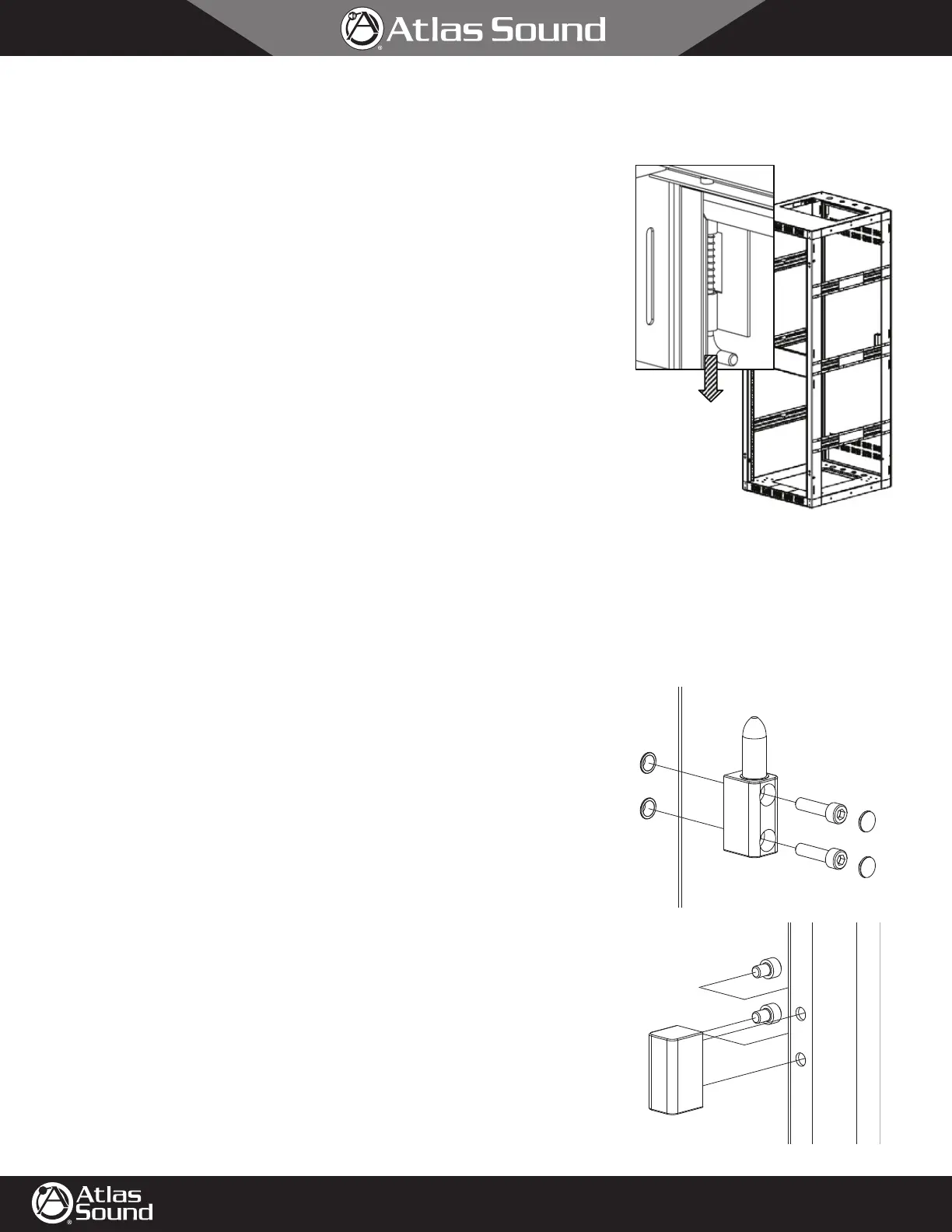
8. Front Door Installation (purchased separately)
DID YOU KNOW? The optional front door (purchased separately) may be hung left or right- hinged
as required by the final installation. The key lock rotation may also be changed.
NOTE: Interference could exist between racked-equipment and door. See Initial Rail Setup section
before proceeding.
a. Orient the door, as it will be mounted on the cabinet. The hinge side will be opposite
from the handle and lock.
b. On the hinge side, remove the 4 caps protecting the door installation points on the cabinet.
These may be discarded.
c. On the cabinet, mount the male hinge with the pins facing up. Use the two longer
10-32 x .75" cap screws found in the hardware bag to mount each male hinge. Install using
a
5
⁄32 hex driver key.
d. Install the two screw covers provided in the hardware bag on each male hinge.
e. Eight (8) holes are located on the hinge side of the door. There are four (4) holes near the
top and four (4) holes near the bottom. Mount the female hinge on the door using the
shorter 10-32 x .25" cap screws provided in the hardware bag. The hinge will mount on the
upper two (2) holes of the four (4) holes found near the top. The second hinge will mount
on the upper two (2) holes of the four (4) holes found near the bottom. In each case, the
female hinge will be mounted with the hinge-hole facing down. Due to the limited space, it
is best to use a L-Shaped
5
⁄32 hex key.
f. Mount door to cabinet.
5. Initial Door Setup:
NOTE: The rear flush door (typically supplied with most
cabinets) may be hung left or right-opening as required by the
final installation. However, the rear door may not be installed
on the front of the cabinet.
a. Remove rear door by pulling the spring-loaded Cane Bolts towards the
center of the door.
b. Be sure nylon gap washer located at the bottom of the door is retained.
c. Flip door as required.
d. Install the door into position with the nylon gap washer located at the
bottom of the door.
To Remove
e. Be sure spring-loaded Cane Bolts actuate to their outward position.
6.
Floor Installation:
NOTE: It is easiest to install cabinet before loading. Otherwise,
be sure adequate room exists to get tooling into the bottom
areas of the cabinet.
a. Always install cabinet on a level surface and suitably anchored in all (4) corners.
b. All cabinets have (4) corner holes at ½” diameter will each accommodate a 3/8” to 7/16” diameter bolt passing through the
steel bottom panel that is spaced 2” to 3” from the floor or directly on the floor (depending on model). The 700 Series
cabinets also have an additional (2) holes located in each bottom corner. FMA Series cabinets have only (2) holes in
each corner.
700 Series Bottom Corner 100, 200, and 500 Series
Bottom Corner
FMA Bottom Corner
P/N 491548 Rev A
To Remove
 Loading...