This document describes the Atlas Sound 100, 200, 500, 700, and FMA Series floor-standing cabinets, which are designed for housing and organizing electronic equipment. These cabinets are suitable for various applications, from basic equipment storage to seismic-rated installations.
Function Description
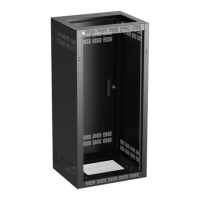
The Atlas Sound floor-standing cabinets serve as robust enclosures for electronic equipment, offering protection, organization, and accessibility. They are designed to be installed on the floor and can be configured with various accessories such as doors, side panels, fan tops, and caster kits to meet specific installation requirements. The cabinets provide a structured environment for mounting rack-mountable equipment, ensuring proper ventilation and security.
Important Technical Specifications
Load Capacity:
- Empty cabinets can weigh up to 200 lbs.
- Caster Kits (purchased separately) for 100, 200, 500, and 700 Series cabinets have a load capacity of 1000 lbs.
- FMA Caster Kits have a load capacity of 880 lbs.
- For seismic applications, 700 Series cabinets with properly installed SBK-700 bracket kits can support up to 625 lbs. of equipment during a Zone 4 earthquake motion (Richter Magnitude 8.0 equivalent).
Hardware:
- Rack screws: 10-32 screws with captive washers are typically used for mounting equipment.
- Phillips cross-drive screws (4) 10-32 are used for metal shipping stiffeners.
- Hex socket driver (3/8") is used for rail adjustments, with a recommended torque of 82 ± 2 in-lbs.
- Carriage bolts (1/4-20 x .625") and KEPS nuts (1/4-20) are used for caster installation.
- Floor installation typically uses 5/16-18 grade 5 hardware, 5/16" fender washers, and split ring lock washers.
Dimensions and Configurations:
- Rack Units (RU) and Load Capacity:
- 1 RU: 25 lbs (front rail max), 56 lbs (use front + rear rail max)
- 2 RU: 50 lbs (front rail max), 112 lbs (use front + rear rail max)
- 3 RU: 75 lbs (front rail max), 168 lbs (use front + rear rail max)
- 4 RU: 100 lbs (front rail max), 224 lbs (use front + rear rail max)
- n RU: n x 25 lbs (front rail max), n x 56 lbs (use front + rear rail max)
- Rack Rails:
- RR21: RAIL PR 21RU 36H BLK
- RR24: RAIL PR 24RU 42H BLK
- RR35: RAIL PR 35RU 61H BLK
- RR40: RAIL PR 40RU 70H BLK
- RR44: RAIL PR 44RU 77H BLK
- FMA-RRK35: RAIL PR 35RU 61H FMA BLK
- FMA-RRK44: RAIL PR 44RU 77H FMA BLK
- Shelf Support Brackets:
- SHRSB2: SHF BRKT RR SPT 2RU SH15/SH22 #052
- SHRSB3: SHF BRKT RR SPT 3RU SH15/SH22 #052
- SHRSB4: SHF BRKT RR SPT 4RU SH15/SH22 #052
- Pull-Out Drawers:
- SD2-14: STORAGE DRAWER - RECESSED 2RU W/ 14" #052
- SD3-14: STORAGE DRAWER - RECESSED 3RU W/ 14" #052
- SD4-14: STORAGE DRAWER - RECESSED 4RU W/ 14" #052
- SD6-14: STORAGE DRAWER - RECESSED 6RU W/ 14" #052
- Lock Kit for Recessed 14" Deep Drawer:
- SD-LOCK: LCK SD DRWR BLK W/B399A KEY
- Caster Kits:
- CT1020-962: ROL TRK 100/200-18 #962
- RCK-18: KIT, ROL TRK 100/200-18
- RCK-25: KIT, ROL TRK 100/200-25
- RCK-30: KIT, ROL TRK 200/500-30
- RCK-700: CSTR SWV NON/LOCK (4) 255 LBS
- FMA-RTK25: KIT, ROL TRK FMA25 220LB
- FMA-RTK36: KIT, ROL TRK FMA36 220LB
- Front Doors:
- SFD21: DOR SUR 21RU 36H 20W 1D #962
- SFD24: DOR SUR 24RU 42H 20W 1D #962
- SFD35: DOR SUR 35RU 61H 20W 1D #962
- SFD40: DOR SUR 40RU 70H 20W 1D #962
- SFD44: DOR SUR 44RU 77H 20W 1D #962
- MPFD21: DOR SUR VNT 21RU 36H 20W 1D #962
- MPFD24: DOR SUR VNT 24RU 42H 20W 1D #962
- MPFD35: DOR SUR VNT 35RU 61H 20W 1D #962
- MPFD40: DOR SUR VNT 40RU 70H 20W 1D #962
- MPFD44: DOR SUR VNT 44RU 77H 20W 1D #962
- PFD21: DOR SUR PLX 21RU 36H 20W 1D #962
- PFD24: DOR SUR PLX 24RU 42H 20W 1D #962
- PFD35: DOR SUR PLX 35RU 61H 20W 1D #962
- PFD40: DOR SUR PLX 40RU 70H 20W 1D #962
- PFD44: DOR SUR PLX 44RU 77H 20W 1D #962
- Side Panels:
- SPS35-25: SDE PNL 500/700 35RU 61H 25D PR #962
- SPS40-25: SDE PNL 500/700 40RU 70H 25D PR #962
- SPS44-25: SDE PNL 500/700 44RU 77H 25D PR #962
- SPS44-30: SDE PNL 500/700 44RU 77H 30D PR #962
- SPS44-36: SDE PNL 500/700 44RU 77H 36D PR #962
- FMA35-25LRPV: PNL SD 35RU 25D CR BLK FMA #962
- FMA44-25LRPV: PNL SD 44RU 25D CR BLK FMA #962
- FMA44-36LRPV: PNL SD 44RU 36D CR BLK FMA #962
- Top and Fan Panels:
- EFT6-4: 6RU FAN PANEL #962
- EFT-25: FAN TOP PANEL FOR 25.5" DEEP CABINET #962
- EFT-30: FAN TOP PANEL FOR 30" DEEP CABINET #962
- EFT-36: FAN TOP PANEL FOR 36" DEEP CABINET #962
- EFP3-1: 3RU FAN PANEL WITH 1 FAN #052
- EFP3-2: 3RU FAN PANEL WITH 2 FANS #052
- Security Panels:
- SEC1: 19" RACK MOUNT SECURITY PANEL 1RU #962
- SEC2: 19" RACK MOUNT SECURITY PANEL 2RU #962
- SEC3: 19" RACK MOUNT SECURITY PANEL 3RU #962
Usage Features
Shipping and Unpacking:
- Cabinets are shipped on a wood pallet.
- Requires adequate surrounding space for unloading and a smooth, unobstructed route to the installation site.
- Care must be taken when navigating obstacles; push from the front or back, never from the sides.
- Shipping straps, shrink plastic, and shipping materials must be carefully removed.
- Metal shipping stiffeners (standard 3RU panels) are removed using a #2 Phillips screwdriver and can be repurposed.
- Hardware bags containing door keys, rack rail hardware, and top hardware should be set aside.
Cabinet Orientation:
- The front is identified by the Atlas Sound Logo plug (top left on most models). This plug can be replaced with an Atlas Sound M-1A IR Repeater if a door blocks IR remote control signals.
- The bottom contains mounting points for casters.
- Most cabinets are sold with an installed flush rear door.
Initial Rail Setup:
- 100 Series cabinets have fixed rails and do not require adjustment.
- Adjustable rails in other series can move forward/backward and up/down within the hat-section slot.
- Rails are secured using a 3/8" hex socket driver, torqued to 82 ± 2 in-lbs.
- Front rails should be positioned to allow clearance for front doors and equipment knobs/connections.
- Rear rack rails (if present) are positioned relative to the front rails, ensuring equal gaps at the top and bottom and avoiding interference with the rear door lock.
Door Installation (Purchased Separately):
- Optional front doors can be hung left or right-handed.
- Hinge pins are installed into the cabinet frame.
- The door is mounted onto the hinge pins.
- The male hinge pins are secured with self-tapping screws.
- The female hinge pins are secured with self-tapping screws.
- The door lock orientation can be changed by removing the bolt, lock cam, and 90° washer, reorienting the key, and reassembling.
Leg Levelers (Presence Varies):
- Leg levelers reduce cabinet capacity and are not recommended for full load capacity.
- They can be removed by turning counter-clockwise, especially when mounting to the floor, ganging cabinets, or using caster kits.
Caster Kits (Purchased Separately):
- Best installed on an unloaded cabinet.
- The cabinet should be carefully laid on its side for installation.
- For 700 Series: Install individual casters on diagonal gussets using 1/4-20 x .625" carriage bolts and 1/4-20 KEPS nuts.
- For 100, 200, 500 Series: Locate caster installation points, loosely install 1/4-20 x .625" carriage bolts from inside the cabinet, mount metal stiffener brackets over pairs of points (flanges pointing outwards), and finally attach casters and stiffener brackets with 1/4-20 KEPS nuts.
- CAUTION: Tall rack cabinets are unstable during transport, especially when loaded. Do not move a loaded cabinet on a caster kit. Use appropriate manpower or equipment for safety.
Side Panel Installation:
- Side panels are sold in pairs and can enclose single or ganged cabinets.
- For SPS Series (500 and 700 Series): Hang panels by engaging six hooks into slots on the cabinet frame.
- For security, an SP-LOCK can be purchased separately, or #8 sheet metal screws can be driven through holes in the rear door flange.
Floor Installation:
- Easiest to install cabinet to the floor before loading.
- Requires adequate room for tooling in bottom areas.
- Always install on a level surface, anchored in all four corners.
- For masonry, use a rotary hammer drill with a carbide-tipped bit to create holes for wedge anchors (e.g., ITW Red Head "Multi-Set II", "Trubolt").
- All cabinets have four corner holes for 5/16-18 grade 5 hardware. 700 Series have two additional bottom corner holes. FMA Series have only two holes per corner.
- Use 5/16" fender washers and split ring lock washers for bearing surface and vibration protection.
- CAUTION: Ensure adequate manpower and use eye protection/gloves.
Equipment Installation:
- Equipment is typically mounted using 10-32 screws.
- Start mounting equipment in lower elevations, placing the heaviest equipment at the bottom.
- Avoid blocking cooling vents; leave at least 1RU of space between adjacent equipment. Filler panels can be used for open spaces.
- Rack units are marked on rails; the first set of 3 mounting holes is 1st rack unit.
- CAUTION: Ensure adequate manpower for installing equipment, as weights can reach 80 lbs. or more. The Atlas Sound LAR150 Load-A-Rack tool can assist.
Maintenance Features
General Maintenance:
- Regularly check and maintain all installed components.
- Ensure all screws and bolts are properly torqued to prevent loosening due to vibration or movement.
- Keep cooling vents clear to ensure proper airflow and prevent overheating of equipment.
- Inspect for any signs of wear or damage to the cabinet structure, doors, or panels.
Cleaning:
- Clean the cabinet surfaces as needed to prevent dust buildup, which can affect equipment performance and aesthetics. Use appropriate cleaning agents that will not damage the finish.
Parts Replacement:
- The manual provides a comprehensive list of accessories and replacement parts, including rack rails, shelves, drawers, doors, side panels, fan tops, and security panels. This facilitates easy identification and ordering of necessary components for repair or upgrade.
Warranty and Service:
- Limited Warranty: All Atlas Sound products are warranted for three years from the date of purchase against defects in material and workmanship, except for electronics and control systems (one year), replacement parts (one year), Musician Series stands (one year), and fuses/lamps (no warranty).
- Atlas Sound will repair or replace defective parts/products at its discretion, provided they were used according to instructions and not damaged by improper storage, misuse, accident, or unauthorized modifications.
- Service: For service, contact the Atlas Sound warranty department at 1-877-689-8055, ext. 277, or support.atlassound.com to obtain an RA number.
- Tech Support: Atlas Sound Tech Support can be reached at 1-800-876-3333 or support.atlassound.com.