8.8.3232 HyHydrdrauaulilic sc sysysttem em / R/ Repepaiair ir insnstrtrucucttioions ns / H/ Hydydrrauaulliic pc pumump p momototor Ar ALLLL
5.5. RelReleasease the the nue nuts ots on tn the the tererminminals als (po(pos. s. 3 fi3 figugurere 8.148.14). If the motor has a return). If the motor has a return
earth cable the earth connection on the rear end head of the motor earth cable the earth connection on the rear end head of the motor should also beshould also be
released (pos. 4 figurereleased (pos. 4 figure 8.148.14).).
6.6. ReReleleasase the the ree rear ear end hnd heaead (pd (posos. 5 f. 5 figigururee 8.148.14). Make sure that the ). Make sure that the terminals remainterminals remain
in their positions.in their positions.
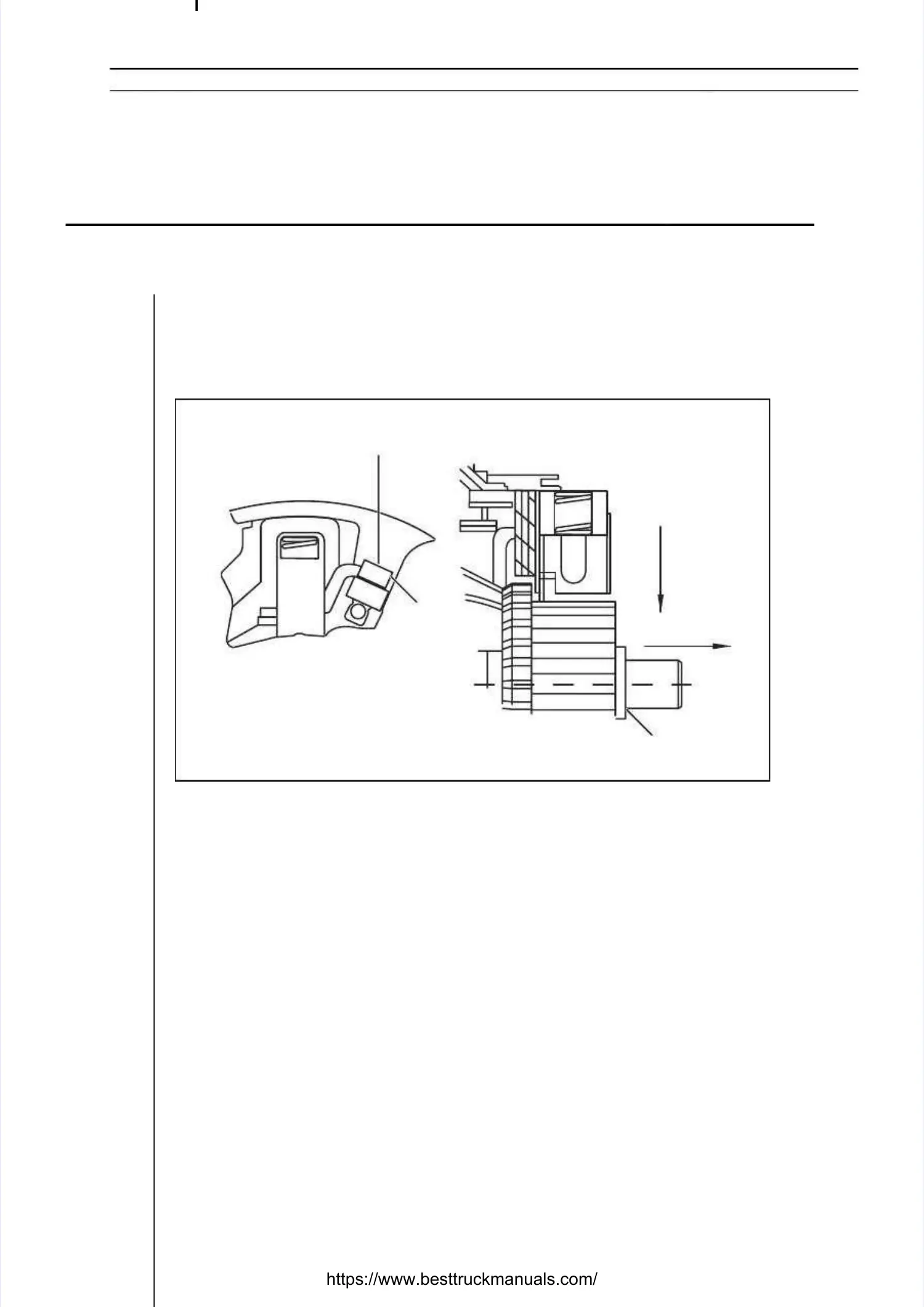
7.7. DiscoDisconnecnnect all t all four four brusbrushes hes by lby loosenoosening ing the sthe screwcrews, pos, pos. s. 1 fig1 figureure 8.158.15- A.- A.
Now press each brush set to the commutator pos. 2 figureNow press each brush set to the commutator pos. 2 figure 8.158.15- B. Remove the- B. Remove the
brush set from the brush rocker - brush set from the brush rocker - C. The old brush set is replaced with a new C. The old brush set is replaced with a new set inset in
the reverse order. It is recommended to replace each brush the reverse order. It is recommended to replace each brush set separately to avoidset separately to avoid
confusion. Make sure that each brush set is replaced with the correct part, iconfusion. Make sure that each brush set is replaced with the correct part, in othern other
words one that has the cable on the correct side. (The service kit words one that has the cable on the correct side. (The service kit consists of twoconsists of two
matching pairs of brush sets!)matching pairs of brush sets!)
8.8. TTigighthten en ththe sce screreww, p, posos. 1 . 1 figfigururee 8.158.15, to approx. 1.3-1.8 Nm., to approx. 1.3-1.8 Nm.
9.9. ReplaReplace the ce the terminterminals in als in the slthe slots in ots in the reathe rear end r end heahead, and, and repld replace iace it on tht on the motoe motorr..
Check that there is a washer between the rotor and end head (pos. 2 figureCheck that there is a washer between the rotor and end head (pos. 2 figure 8.158.15))
and that the holder is held in place with a and that the holder is held in place with a tooth and slot on the casing in the respec-tooth and slot on the casing in the respec-
tive end.tive end.
10.10. Fit the throFit the through boltugh bolts and put the mos and put the motor bactor back in the truck. Tk in the truck. Tighteighten the bolts ton the bolts to
approx. 4.8-6.8 Nm.approx. 4.8-6.8 Nm.
111.1. TigTighten thten the termhe terminals tinals to 10-1o 10-14 Nm (p4 Nm (pos. 3 figos. 3 figureure 8.148.14).).
12.12. ReplaReplace thce the cae cables bles to thto the mote motor teror terminalminals.s.
Figure 8.15Figure 8.15
1
1
AA
BB
CC
22
 Loading...