GK3000 User Manual
.Keyboard
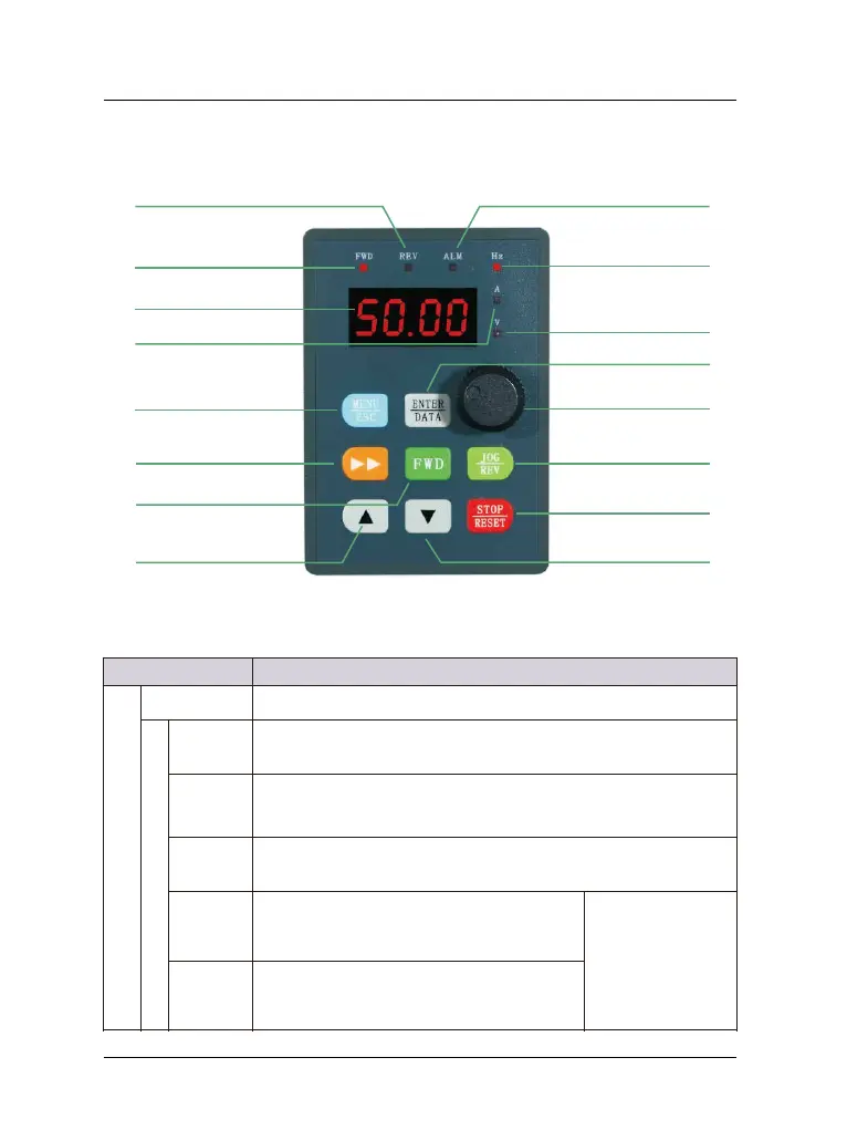
Item Function description
Display function
Digital display Display VFD’s running state parameters and setting parameters
State indicator
A、Hz、V
The physical units correspond to presently digital display par
(current is ampere A, voltage is volt V, frequency is Hertz Hz) .
MOD
In the non-monitoring state, the indicator is on. If there is no press
for one minute, the indicator is off and returns to the monitoring
ALM
The alarm indicator, indicates that the VFD is currently in an
overcurrent or overvoltage state or a fault alarm state.
FWD
Forward indicator, indicates that the VFD
outputs positive phase sequence. When the
motor is connected, the motor rotates forward.
If the FWD and
REV indicators are
on at the same
time, it indicates
that the VFD is
working in DC
REV
Reverse indicator, indicates that the VFD
output reverse phase sequence, when the
motor is connected, the motor is reversed.
Figure 5-1 Control panel diagram
.1 Keyboard indicator
-14-
Forward indicator
Reserve indicator
Alarm fault indicator
Frequency(Hz)
Digital display
Stop/reset key
DOWN key
UP key
Forward key
MENU/ESC key
Function/Data key
Analog potentiometer
Reserve/Jog key
Voltage(V)
Electric current(A)
Shift/monitor
 Loading...