GK3000 User Manual
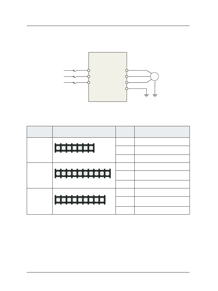
4.1 Main circuit wiring diagram
Figure 4-1 Main circuit wiring
R( )L1
S(L2)
T
M
U
V
W
PE
Circuit
VFD
AC power
4.2 Main Circuit Terminals Diagram
Apply to Main circuit terminal
name
Function
220V
1-phase
0.4KW~5.5KW
L1、L2
220V 1-phase Input terminals
U、V、W
220V 1/3-phase Output
terminals
E Earthing
220V
1-phase
7.5KW~15KW
R&S,R&T
,S&T
220V 1-phase Input terminals
U、V、W
220V 1/3-phase Output
terminals
P+、PB
Braking resistor wiring terminals
220V
1-phase
18.5KW~75KW
220V 1-phase Input terminals
U、V、W
220V 1/3-phase Output
terminals
P+、P-
Braking resistor wiring terminals
L1 L2 E U V W
RS UV
W
T
P-
P+ PB
E
T
P+
S
R UV
W
P-
E
Table 4-1 Description of Main Circuit input/output terminals
&KDSWHUStandard Wiring
-6-
R&S,R&T
,S&T