EasyManua.ls Logo

ATO YT-95H-XX - User Manual

ATO YT-95H-XX
2 pages
Print Icon
To Next Page IconTo Next Page
Loading...
Matters need attention
A. Please read this instruction manual before using the detector.
B. The detector must be used in compliance with the designated procedures of our company.
C. The warranty period of this transmitter is 12months (starts from the date userget the detector).
Users should comply with the instructionsin the use of this detector. Any damages or malfunctions
caused by improperoperation of users are not within the scope of warranty.
D. Repairand replacement of any parts must be operated by trained staff under authorization of
our company, using original spare part. The operatoris responsible for the liability if users operate
the repair of replacement by themselves.
E. There is acid solution inside the transmitter, please do not disassembleit. And pay attention not
to damage the frontal membrane of the transmitter. If the skin is stained with the acid solution. the
right remedy is to flushing the stained skin continuously with clean water for 1 0minutes.
F. The detector must be calibrated for once each year. The explosion proof sheet parts of the
transmitter need to be cleaned regularly (blow with low pressure compressedair), otherwise the
detection sensitivity will be aected by the dust and impurities clogging protection hole.
3
2
1.Power supply, signal line
2.Printed-circuit board
3.Terminal
4.Sound and tight alarm port
5.Air chamber of sensor
6.Sensor port
7.Main board connection
Ground
connectio n port
5
6
1
2
3
4
7
1. Key Technical Indicator
Repeatability: <2%
Zero drift: < ± 2% (F•S) /6M
Operating temperature: -20~+50
Environment temperature: <90%RH
Working principle of the transmitter: electrochemical for oxygen and hazardous gases, catalytic
combustion for combustible gases
Lifespan of transmitter: 3years for combustible gas transmitter; 2years for hazardous gas
transmitter
2. Other Technical Parameters
Inspection mode: diusion
Working mode: fixed long-term continuous work
Working voltage: 12-30V DC
Working current: oxygen and hazardous gas <50mA (Max)
combustible gas <150mA (Max)
Technical performance and parameters
Notice to Reader
Please read this instruction manual before using the detector
Output signal: three-wire 4-20 mA standard signal output or RS485 signal output
Exterior structure: die-casting aluminum housing
Dimensions: 135 x 125 x 116mm (without mounting bracket)
167 x 145 x 126mm (with bracket)
Weight: without mounting brackets 1.2kg with brackets 1.6kg with stent
Connection cable (6 core cable) is defined as follows:
4-20mA with RS485:
Red: positive-input of power (12 to 24V)/ 24V+
Black: ground wire of power/24V
Yellow:4-20mA output.
Orange: RS485A
Blue: RS485B
Brown: Free
Connection distance: >1000m
Protection grade: IP65
Installation type: on wall
Type of explosion-proof: flame proof
Explosion-proof grade: Ex d IIC T6 Gb
Inlet port: hexagonal locknut
Settings of Remote Control
The remote control applied to all product type produced by Yuante.
1. Press "MENU" once to enter F01, address code setting menu. Press "OK" to modify, press"+""-
"to modify address code of the detector. Press "OK" to save settings and "BACK" to cancel.
2. Press "MENU", then press “+”to enter F02, minimum value setting menu of gas alarm, Press
"OK" to modify, press"+" "-"to modify the value. Press "OK" to save settings and "BACK" to
cancel.
3. Continue to press "+"to enter F03, maximum value setting menu of gas alarm., Press "OK" to
modify, press"+" "-"to modify the value. Press "OK" to save settings and "BACK" to cancel. Same
operation with F04 (zero point calibration), F05 (range calibration), F06 (AD value).
4. Press "MENU" four times to enter a shift status, under this status:
Press "RESET" once, the data would be 255, one more it would be 0. Just press "RESET" to shift.
When the data is 0, press "+"or"-"to modify alarm point, the data dierence would be only 1. When
the data is 255, press "+"or"-"to modify alarm point, the data dierence would be 1000. "RESET"
can also be used as mute button when it is alarming.
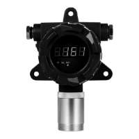
1
4
Fixed Gas Detector
YT-95H-:XX
Instruction Manual
Target gas
Range
Accuracy
least count
response time
O2
0-30%VOL
2%(F.S)
0.01%VOL
15
H2S
0-1000ppm
2%(F.S)
1ppm
15
CO
0-1000ppm
2%(F.S)
1ppm
25
H2
0-20000ppm
2%(F.S)
1ppm
15
CO2
0-10000ppm
2%(F.S)
1ppm
40
C2H4
0-100ppm
2%(F.S)
0.01ppm
60
NO2
0-20.0ppm
2%(F.S)
0.1ppm
25
N2
0-100%VOL
2%(F.S)
0.01%VOL
40
TVOC
0-6000ppm
2%(F.S)
1ppm
60
NH3
0-100ppm
2%(F.S)
0.01ppm
40
ASH3
0-10.00ppm
2%(F.S)
0.01ppm
30
C3H3N
0-200.0ppm
2%(F.S)
0.1ppm
40
F2
0-10 ppm
2%(F.S)
0.01ppm
25
O3
0-5.00ppm
2%(F.S)
0.01ppm
50
CL2
0-10.00ppm
2%(F.S)
0.01ppm
60
BF3
0-10.00ppm
2%(F.S)
0.01ppm
60
NC:Normally close
NO:Normally open
COM:Common
24V:24+,positive
GND:24-,negative
4~20mA:4~20mA analog signal
High Alarm
Low Alarm
RelayRelay
Powered
Signal output
Motherboard connector
Alarm
Digital probe portDigital probe portDigital probe port
Port Instruction
www.ato.com
sales@ato.com
18005851519
Global Shipping
www.ato.com
sales@ato.com
18005851519
Global Shipping
www.ato.com
sales@ato.com
18005851519
Global Shipping
www.ato.com
sales@ato.com
18005851519
Global Shipping
Question and Answer IconNeed help?

Do you have a question about the ATO YT-95H-XX and is the answer not in the manual?

Summary

Matters need attention

Port Instruction

Technical performance and parameters

Key Technical Indicator

Details gas types, ranges, accuracy, least count, and response times for the detector.

Settings of Remote Control

Remote controller function

Function introduction

Details the function codes (F-01 to F-12) for the remote controller's operational menu.

Installation Instruction

1. Location Selection

Provides guidance on selecting an appropriate location for the gas detection transmitter.

2. Steps of Installation

Outlines the procedure for installing the detector, including wiring connections.

Method of Calibration

1. Zero Point Calibration

Explains the process for calibrating the detector's zero point in clean air.

2. Range Calibration

Details the steps for calibrating the detector's measurement range using standard gas.

Common Malfunction, Repair and Maintenance

Overview

The ATO Fixed Gas Detector, model YT-95H-:XX, is a robust and reliable instrument designed for continuous, long-term monitoring of various gases. This device is crucial for safety in environments where gas leaks or specific gas concentrations need to be precisely measured and alarmed.

Function Description

The primary function of the YT-95H-:XX is to detect and measure the concentration of a target gas in the air using a diffusion inspection mode. It provides real-time gas concentration readings and features both low and high alarm points to alert users to potentially dangerous conditions. The detector offers two main output signals: a standard three-wire 4-20 mA analog output and an RS485 digital signal output, allowing for flexible integration into various control systems. It also includes relay outputs for low and high alarms, enabling direct control of external alarm devices or ventilation systems.

The device is equipped with a remote control for easy configuration and calibration. The remote control allows users to access and modify various parameters, including address code, low and high alarm set points, zero point calibration, 4mA offset correction, ADC check, standard gas concentration, calibration switch, production date, reserved functions, serial communication check (odd, even, or no check), and arrangement mode of floating-point data (DCBA, ABCD, or CDAB). All parameter changes made via the remote control take effect immediately and are saved even after a power outage.

Important Technical Specifications

  • Target Gases and Ranges: The detector supports a wide range of gases with specific detection ranges and accuracies:
    • O2: 0-30%VOL, <±2%(F.S), 0.01%VOL least count, ≤15s response time
    • H2S: 0-1000ppm, <±2%(F.S), 1ppm least count, ≤15s response time
    • CO: 0-1000ppm, <±2%(F.S), 1ppm least count, <25s response time
    • H2: 0-20000ppm, <±2%(F.S), 1ppm least count, ≤15s response time
    • CO2: 0-10000ppm, <±2%(F.S), 1ppm least count, ≤40s response time
    • C2H4: 0-100ppm, <±2%(F.S), 0.01ppm least count, ≤60s response time
    • NO2: 0-20.0ppm, <±2%(F.S), 0.1ppm least count, ≤25s response time
    • N2: 0-100%VOL, <±2%(F.S), 0.01%VOL least count, ≤40s response time
    • TVOC: 0-6000ppm, <±2%(F.S), 1ppm least count, ≤60s response time
    • NH3: 0-100ppm, <±2%(F.S), 0.01ppm least count, ≤40s response time
    • ASH3: 0-10.00ppm, <±2%(F.S), 0.01ppm least count, ≤30s response time
    • C3H3N: 0-200.0ppm, <±2%(F.S), 0.1ppm least count, ≤40s response time
    • F2: 0-10 ppm, <±2%(F.S), 0.01ppm least count, ≤25s response time
    • O3: 0-5.00ppm, <±2%(F.S), 0.01ppm least count, ≤50s response time
    • CL2: 0-10.00ppm, <±2%(F.S), 0.01ppm least count, ≤60s response time
    • BF3: 0-10.00ppm, <±2%(F.S), 0.01ppm least count, ≤60s response time
  • Repeatability: <2%
  • Zero Drift: <± 2% (FS) /6M
  • Operating Temperature: -20~+50°C
  • Environment Humidity: <90%RH
  • Working Principle: Electrochemical for oxygen and hazardous gases; catalytic combustion for combustible gases.
  • Lifespan of Transmitter: 3 years for combustible gas transmitter; 2 years for hazardous gas transmitter.
  • Working Voltage: 12-30V DC
  • Working Current: Oxygen and hazardous gas <50mA (Max); combustible gas <150mA (Max).
  • Output Signals: Three-wire 4-20 mA standard signal output or RS485 signal output.
  • Exterior Structure: Die-casting aluminum housing.
  • Dimensions: 135 x 125 x 116mm (without mounting bracket); 167 x 145 x 126mm (with bracket).
  • Weight: 1.2kg (without mounting brackets); 1.6kg (with brackets).
  • Connection Cable (6 core cable) definition:
    • Red: positive-input of power (12 to 24V)/24V+
    • Black: ground wire of power/24V
    • Yellow: 4-20mA output
    • Orange: RS485A
    • Blue: RS485B
    • Brown: Free
  • Connection Distance: >1000m
  • Protection Grade: IP65
  • Installation Type: On wall
  • Type of Explosion-Proof: Flame proof
  • Explosion-Proof Grade: Ex d IIC T6 Gb
  • Inlet Port: Hexagonal locknut

Usage Features

  • Installation: The detector is designed for wall mounting using expansion bolts. It is crucial to ensure the transmitter is positioned downward for proper operation. Users can separate the bracket from the transmitter for easier installation. For safety and interference reduction, the housing must be connected to a reliable ground wire. The connection cable between the transmitter and the main engine should be as short as possible and protected with an iron pipe.
  • Location Selection: Optimal detection results depend on careful location selection. Factors to consider include:
    • Gas density at the leaking point.
    • Proportion of the target gas.
    • Impact of surrounding buildings.
    • Condition of production equipment.
    • Wind direction and annual meteorological conditions.
    • Location of windows and doors in indoor environments.
    • Maintain a proper distance from the possible gas leaking point to avoid overly fast or frequent reactions.
    • The detector should be located downwind of the possible leaking point.
    • If installed indoors, but the leak source is outdoors, the detector must be installed at the air inlet.
    • Determine installation height based on the target gas's proportion in the air.
    • Determine the quantity of detectors based on possible leaking points, staff attendance frequency, stay time, and economic considerations.
    • Consider increasing inspection points for older equipment.
    • Protect the detector from high-temperature heat sources, as extreme temperatures (both high and low) can affect results and lifespan.
  • Remote Control Operation: The remote control provides a user-friendly interface for configuring the detector.
    • Menu Navigation: Press "MENU" to enter the functional state. Use "+" and "-" to navigate through functions (F01 to F12).
    • Parameter Modification: Press "OK" to modify a parameter, use "+" and "-" to adjust the value, then press "OK" to save or "BACK" to cancel.
    • Alarm Reset: Press "RESET" to eliminate the alarm function.
    • Shift Status: Press "MENU" four times to enter a shift status. In this status, pressing "RESET" toggles data between 255 and 0. When data is 0, "+" or "-" modifies the alarm point with a difference of 1. When data is 255, "+" or "-" modifies the alarm point with a difference of 1000. "RESET" also functions as a mute button during an alarm.

Maintenance Features

  • Calibration: Regular calibration is essential to ensure measurement accuracy.
    • Zero Point Calibration (F-04): In a clean air environment, access F-04 via the remote control and click "OK" to perform zero calibration. For oxygen detectors, nitrogen with purity over 99.99% must be used.
    • Range Calibration (F-07, F-08):
      1. Set the standard gas concentration in F-07 (default is half of the measure range) using "+" and "-". Press "OK" to exit.
      2. Change F-08 from 0 to 1, then return to the detection interface.
      3. Connect 200-400mL/min standard gas to the detection interface. Once the detector value stabilizes, press "OK" for 3 seconds to automatically calibrate. The measured concentration will match the value set in F-07.
      4. After calibration, leave the detector in the air until its value is close to zero, then shut off the power.
    • Calibration Devices: Required devices include a sample gas bottle (60%F.S standard gas), relief valve, flow meter (0~1000ml/min), transparent conduit, standard gas housing, digital multimeter, and stopwatch.
    • Factory Settings: The transmitter's WB (4mA), WC (20mA), Wz (zero potentiometer), WA (range potentiometer), and host alarm values are set at the factory and should not be casually adjusted by users.
  • Troubleshooting: The manual provides a common malfunction table with symptoms, reasons, and repair methods:
    • No output: Check for wrong connection, incorrect reference point potential, or circuit fault. Solutions include reconnecting, adjusting zero point and potentiometer, or returning for repair.
    • Too low host reading: May be due to the S potentiometer setting being too small or transmitter failure. Solutions include recalibrating or replacing the transmitter.
    • Too high host reading: May be due to the S potentiometer setting being too large or transmitter failure. Solutions include recalibrating or replacing the transmitter.
    • Instable host reading: May be due to insufficient heat settling time, transmitter failure, or circuit fault. Solutions include waiting for startup, replacing the transmitter, or returning for repair.
  • General Maintenance:
    • The detector must be used in compliance with the designated procedures.
    • The warranty period is 12 months from the date of purchase. Damages due to improper operation are not covered.
    • Repairs and part replacements must be performed by trained staff authorized by the company, using original spare parts. Unauthorized repairs will void liability.
    • Do not disassemble the transmitter, as it contains acid solution. Avoid damaging the frontal membrane. If skin comes into contact with acid, flush continuously with clean water for 10 minutes.
    • The detector must be calibrated annually.
    • Explosion-proof parts of the transmitter should be regularly cleaned (blown with low-pressure compressed air) to prevent dust and impurities from clogging protection holes and affecting detection sensitivity.

ATO YT-95H-XX Specifications

General IconGeneral
BrandATO
ModelYT-95H-XX
CategoryGas Detectors
LanguageEnglish