2
FOR YOUR SAFETY
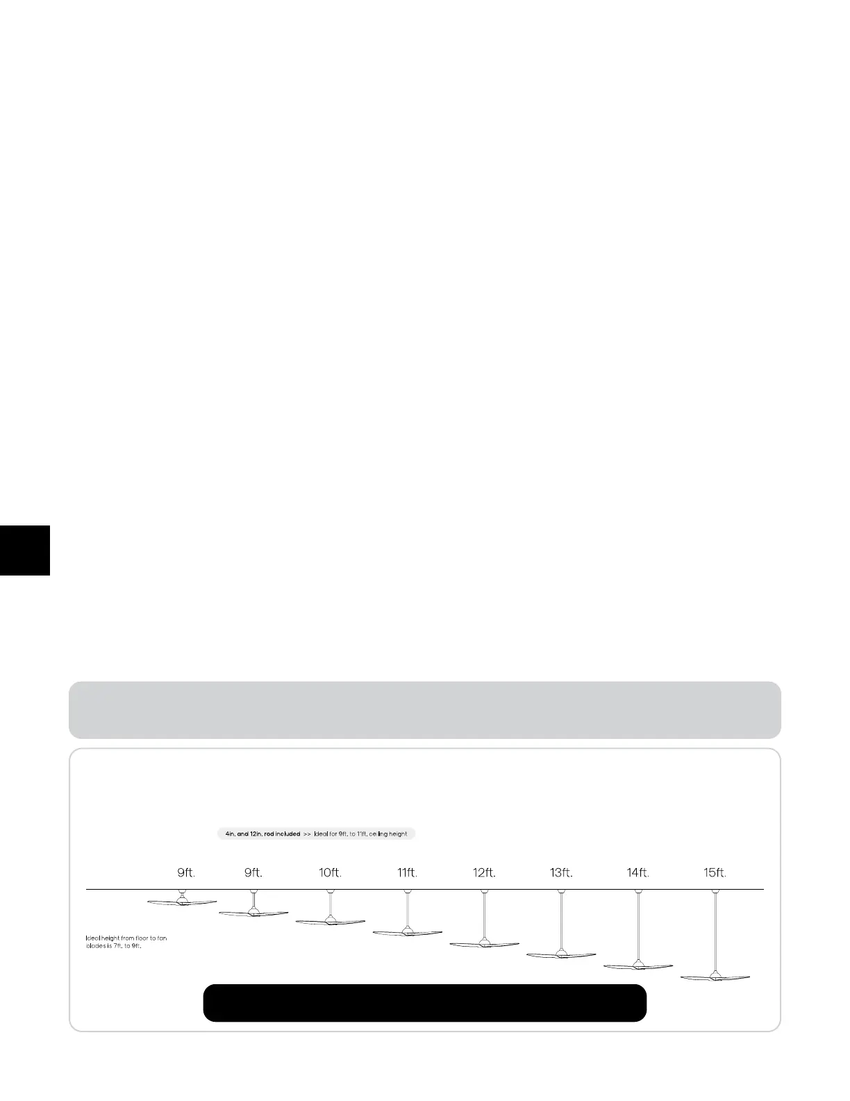
Know your ceiling height
Downrod Length
Ceiling Height
Flush mount /
Close mount
Less
than
2.74m
Up to 12in.
Downrod
2.74m
Up to 18in.
Downrod
3.04m
Up to 24in.
Downrod
3.35m
Up to 36in.
Downrod
3.65m
Up to 48in.
Downrod
3.96m
Up to 60in.
Downrod
4.26m
Up to 72in.
Downrod
4.57m
Mounting to high ceilings?
Maximize your comfo by choosing the right accessory downrod length for your ceiling.
If you have an angled ceiling, you may need a longer downrod.
Visit www.atomisma.com to find additional downrod options.
Caution: Modifications not approved by the pay responsible for compliance could void user’s
authority to operate the equipment.
1. To reduce the risk of personal injury, do not bend the blade brackets when installing the brackets, balancing the
blades, or cleaning the fan. Do not inse foreign objects in between rotating fan blades.
2. To reduce the risk of fire, electric shock, or personal injury, mount directly to a structural framing member or to an
outlet box marked “acceptable for fan suppo of 31.8kg (70lb) or less”. For outlet box mounting, use mounting
screws provided with the outlet box.
3. The fan can be mounted to a structural framing member or an outlet box. When mounted to an outlet box, use
the screws provided with the outlet box.
4. The installation is in accordance with the National Electrical Code, ANSI/NFPA 70, and local codes.
5. To avoid possible electrical shock, before installing or servicing your fan, disconnect the power by turning o the
circuit breaker to the outlet box and associated wall switch location.
6. To reduce the risk of electric shock, this fan must be installed with an isolating wall control/switch.
7. The wall switch used shall have been investigated and found acceptable for use as a general-use switch.
8. Aer making the wire connections, the wires should be spread apa with the grounded conductor and the
equipment-grounding conductor on one side of the outlet box and the ungrounded conductor on the other side
of the outlet box.
9. Aer the splices are made, they should be turned upward and pushed carefully up into the outlet box.
10. A grounded conductor is to be connected to a grounded conductor of power supply, a conductor of fan
identified as ungrounded conductor is to be connected to an ungrounded conductor of power supply, and a
conductor of fan identified for equipment grounding is to be connected to an equipment-grounding conductor.
11. To reduce the risk of electric shock, disconnect the electrical supply circuit to the fan before installing the light kit.
12. This appliance is not intended for use by persons (including children) with reduced physical, sensory, or mental
capabilities, or lack of experience and knowledge unless they have been given supervision or instruction
concerning use of the appliance by a person responsible for their safety.
13. Children should be supervised to ensure that they do not play with the appliance.
14. To avoid any accidental losses, all set screws must be checked and retightened, where necessary,
before installation.
15. Before installation, check that the outlet box is securely installed in place such that it is able to suppo at least
the fan weight.
READ AND SAVE ALL INSTRUCTIONS BEFORE USING.
WARNING
 Loading...