Do you have a question about the attocube ASC500 and is the answer not in the manual?
Provides an overview of the ASC500 SPM controller and its capabilities.
Details critical safety precautions for operating the ASC500.
Instructions for physically setting up the ASC500 controller.
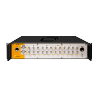
Identifies and describes all physical connectors on the ASC500.
Explains the functionality of the manual control iBox accessory.
Lists detailed technical specifications of the ASC500 hardware.
Step-by-step guide for installing the necessary hardware drivers.
A concise guide on how to save data from the ASC500.
In-depth explanation of data management, channels, and processing.
Covers software installation and initial setup for the Daisy program.
Overview of the Daisy software interface and its main components.
Explains common GUI elements like text boxes and context menus.
Configuration of controller outputs and voltage limits.
Manages scan parameters and area settings.
Details the Z-axis feedback control for precise positioning.
Covers advanced functions like PLL, coarse motion, and spectroscopy.
Procedures for routine safety checks and testing.
Guidelines for cleaning the ASC500 unit.
| Model | ASC500 |
|---|---|
| Type | Controller |
| Closed-loop control | Yes |
| Interface | USB, Ethernet |
| Control Modes | Position, Velocity |
| Feedback Sensors | Optical |
| Frequency Range | 0 to 1 kHz |
| Storage Temperature | -20°C to +70°C |
| Number of axes | 1 to 3 |
| Voltage Range | -10 V to 10 V |
| Operating Temperature | 0 to 50 °C |