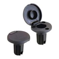
Plastic Stowaway Light Base
91020, 91022 (2 wire)
91021 (3 wire)
Installation Instructions
Attwood marine hardware, navigational lighting, bilge pumps, and
other marine accessories are specified more than any other brand by
America’s best-known boat manufacturers as original equipment.
Look to Attwood for quality replacement parts and marine accessories.
SAVE THESE INSTRUCTIONS
Form Number 69345 Rev. C 03-12
3
®
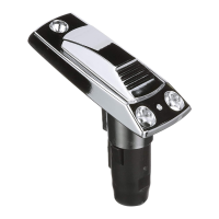
3. Apply sealant between deck and light base. Fasten base in place
with stainless steel screws.
CAUTION
Do not overtighten screws.
Figure 2
FEATURES
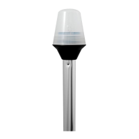
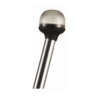
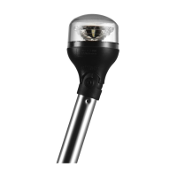
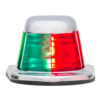
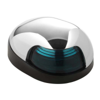
This base is designed for use with the Attwood 3900 Series All-
Round Lights And Attwood Combination Sidelights.
For 12-volt D.C. only.
CAUTION
To prevent personal injury, always disconnect the power source
when installing or servicing this product. Always remove the boat
from the water before using 120 VAC power tools.
INSTALLATION INSTRUCTIONS
Note: For technical detailed positioning follow COLREG 72 or ABYC
A-16. Below is a simplified drawing of placement of navigational
lights in relationship to one another. (Figure 1)
Figure 1
1. Position the light base either on the bow for combination sidelights
or the stern or gunwale for all-round lights. Be sure that the
mounting surface is flat and that the selected area will accommo-
date the base dimensions. Base angle and position must properly
place light used in base.
3/4"
1-1/2"
Forward
1-1/4"
27/32"
1-1/4"
3/4"
15/16"
1-3/4"
1"
15/32"
1-3/8"
Forward
2. Using the template provided, locate the base center line parallel
to the boat fore-and-aft center line and carefully mark the center
installation hole and the screw holes. Drill 1-3/8'' diameter hole for
#91022 or 1-1/4" diameter hole for #91020 and #91021 being very
careful not to crack or break the gelcoat finish, and sand to remove
burrs from around the edge of the hole. Drill the pilot screw holes.
(Figure 2)
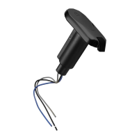
Note: On some installations you may have to connect the wires then
push them back through wire hole prior to screwing down the base.
Oval Template
Round Template