1
ENGLISH, FRANCAIS (et Canada) •Installation •Maintenance
Effective 1/08
LITERATURE NUMBER
MPD 33179
hydro flame
TM
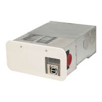
8500-IV Series Furnace
MODELS 8516, 8520, 8525,
8531, 8535
Technical Installation Manual
9
WARNING
FIRE OR EXPLOSION
• If the information in this manual is not followed
exactly, a fire or explosion may result causing
property damage, personal injury or loss of life.
FOR YOUR SAFETY
WARNING
FIRE OR EXPLOSION
WHAT TO DO
IF YOU SMELL GAS
• Evacuate ALL persons from vehicle.
• Shut off gas supply at gas container or source.
• DO NOT touch any electrical switch, or use any phone or
radio in vehicle.
•
DO NOT start vehicle’s engine or electric generator.
• Contact nearest gas supplier or qualified Service Technician
for repairs.
• If you cannot reach a gas supplier or qualified Service
Technician, contact the nearest fire department.
•
DO NOT turn on gas supply until gas leak(s) has been repaired.
Installation and service must be performed by a qualified
Service Technician, Service Center or gas supplier.
THIS INSTRUCTION MANUAL IS FOR USE BY AN AUTHORIZED SERVICE
TECHNICIAN TO INSTALL AN ATWOOD
- hydro flame
TM
FURNACE.
TO THE INSTALLER: THESE INSTRUCTIONS MUST BE SUPPLIED WITH THE FUR-
NACE TO THE CONSUMER.
TO THE CONSUMER: PLEASE RETAIN THESE INSTRUCTIONS FOR FURTHER REFER-
ENCE.
This furnace design has been certified for installation in recre-
ation vehicles as a MSP Category III furnace. Follow this installa-
tion instruction to insure safe operation of the furnace. Failure to
install furnace according to this installation instruction nullifies
the furnace warranty.
SAFETY ALERT SYMBOLS
Safety Symbols alerting you to potential personal safety hazards.
Obey all safety messages following these symbols.
WARNING CAUTION
avoid possible avoid possible
injury or death injury and/or property damage
INDEX
FURNACE SPECIFICATIONS ..............................................................1
DIMENSIONS ..................................................................1
WEIGHT ........................................................................1
MINIMUM CLEARANCE TO FLOORBOARDS, WALLS,
& SIMILAR COMBUSTIBLE BUILDING MATERIALS..................................2
SAFETY INFORMATION..................................................................1-2
FURNACE INSTALLATION ..................................................................2
WALL CUTOUTS ..........................................................................2
DUCTING................................................................................2-3
Required Minimum Discharge Chart ............................................3
Flexible Ducting......................................................................3
Floor Ducting ........................................................................3
OPTIONAL INSTALLATION - BOTTOM DISCHARGE KIT..................................3
OPTIONAL INSTALLATION - EXTENSION BOX KIT ......................................3
OPTIONAL INSTALLATION - FLEX ADAPTER KIT........................................3
PROPANE GAS CONNECTION ............................................................
3
ELECTRICAL CONNECTIONS..............................................................
3
Conductor Sizing Table ............................................................3
Thermostat Installation ............................................................4
DOOR INSTALLATION ....................................................................4
Horizontal and Vertical Door Option ............................................4
Recess Bezel Door Option ........................................................4
DRAFT CAP ASSEMBLY ..................................................................4
OPTIONAL FURNACE INSTALLATION - Recessed Furnace........................4-5
SYSTEM CHECK TESTS ....................................................................5
PROPANE GAS PRESSURE ..............................................................5
STATIC PRESSURE ........................................................................5
DC WIRING DIAGRAM......................................................................5
ILLUSTRATIONS ............................................................................6
REPLACEMENT PARTS LIST & DRAWING ..............................................7
SPECIFICATIONS (W.C. = Water Column)
MODEL # 8516-IV 8520-IV 8525-IV 8531-IV 8535-IV
BTU Input 16,000 20,000 25,000 30,000 34,000
Duct Static Pressure .20˝ W.C.* .10˝ W.C.* .10˝ W.C.* .10˝ W.C.* .10˝ W.C.*
12 Volt Amperage (AMPS) 4.6 4.6 7.6 7.6 9.8
Watts 55 55 91 91 118
Power Supply (
VOLT DC)12 12 12 12 12
Recommended Return Air 80 in
2
80 in
2
80 in
2
80 in
2
80 in
2
MINIMUM RETURN AIR 65 in
2
65 in
2
65 in
2
65 in
2
65 in
2
DIMENSIONS
WEIGHT
ALL MODELS WIDTH HEIGHT DEPTH
Casing 16-1/2˝ 7-3/8˝ 18˝ FURNACE 30 lbs
Door 19-1/4˝ 9-1/4˝ 1/4˝ SHIPPING 32 lbs
Recess Bezel 20-9/16˝ 11-1/2˝